SWR Power meter with protection for Solid State PA
Also usable as a dual mW meter with a few changes in the software.
Introduction
This SWR Power meter was my first own project for the Arduino. I started it from scratch and decided to build an accurate Power meter for the directional coupler described HERE. This meter had to be suitable for a large power range. I used my experience from early days with the AD8307 log detector chip from Analog Devices. (HERE) This chip is suitable up to 500 MHz and has a very high dynamic range. It can measure almost from almost the noisefloor (-74dBm or even lower) up to 10 mW where the upper range is less accurate, so we better stay away from that. The measurement accuracy is excellent. With a dynamic range of 88dB the accuracy is 1dB according to the data sheet. This accuracy is also valid for the SWR-Power meter if your calibration is accurate. But even without calibration this power / SWR meter is better than most of the commercial available SWR Power meters.
The first steps showed very nice results and I build a number of SWR-Power meters to replace the older gear in my shack. They worked very well and I am still using them. In a conversation with Wim PA0WMX he suggested a few protection circuit features to be build in as well. More and more the idea developed and it now has SWR protection, temperature protection and a blower speed control. There are also 2 current protection circuits and a voltage protection. This is the maximum I could use with my programming skills, there were no pins left on the Atmega328.
Wim PA0WMX needed some boards and so did I, so we decided to design a board and we had it made professionally. See some pictures below.
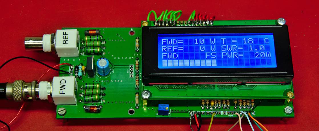
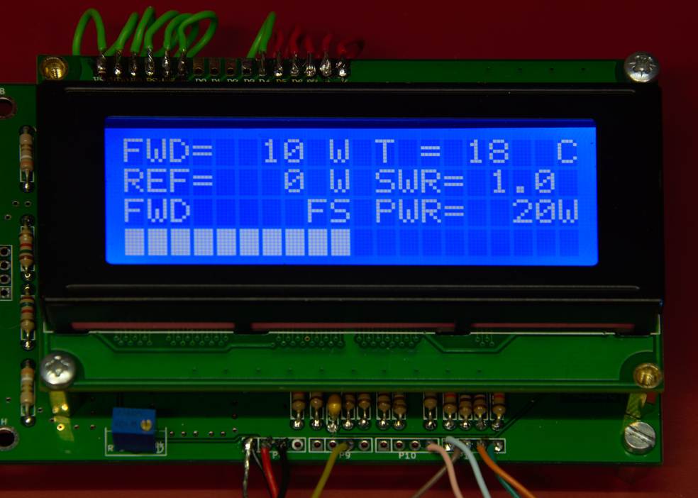
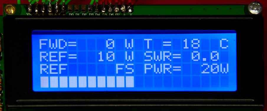
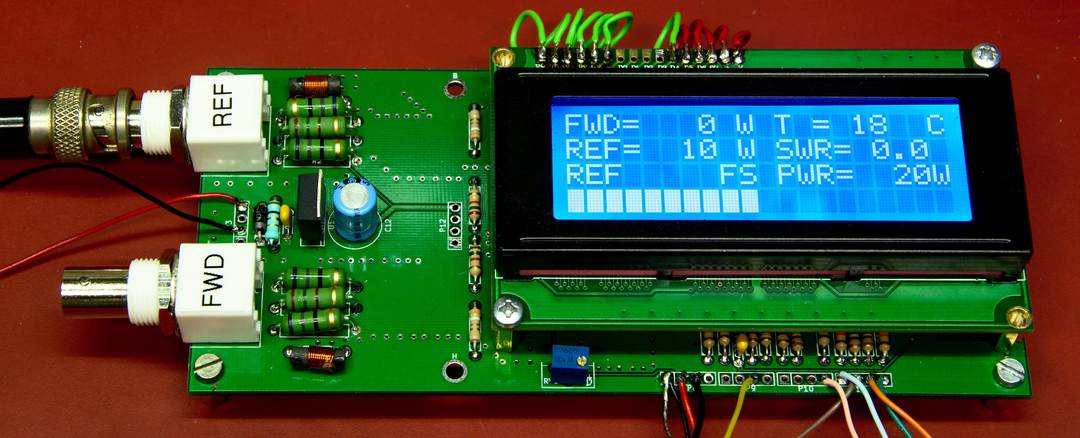
The first line of the display shows the forward power and the temperature
The second line shows the reflected power and the calculated SWR
The third line shows the mode and the full scale power of the bar graph which is on the fourth line.
Short description of the buttons
The unit has 3 buttons:
#1. is the reset button in case of an alarm, you can only reset the protection circuitry with this button. Alarms are set at SWR 1:2 and temperature at 45 degrees C. You can change these values in the software. If you push this button it will pause for few seconds and than the greeting screen will show for 1 second.
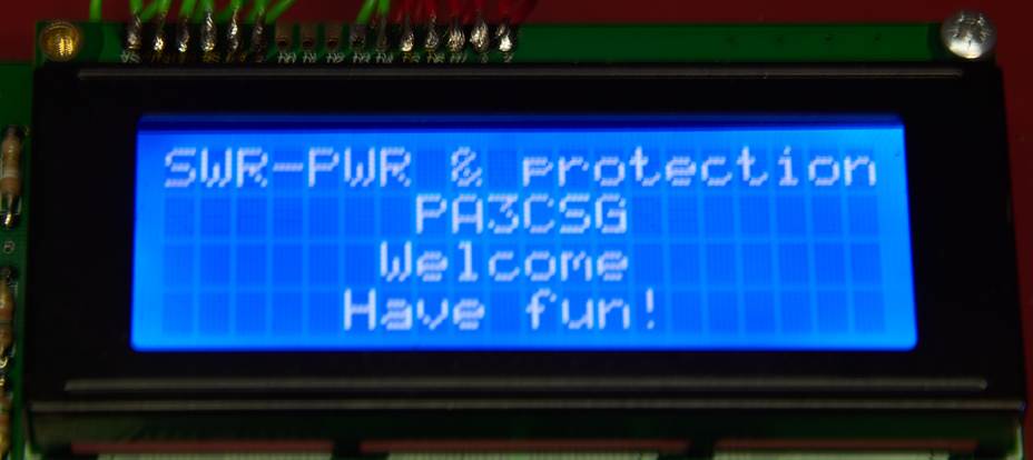
The greeting screen:
#2. Is the Mode button. With this button you will change from Forward ( the third line will show FWD), Second mode is Reflected (REF) and Third mode is Temp. In FWD mode the bargraph will display FWD power, In REF mode the bar graph will display REF power, in third mode the bar graph will show Temperature from 0-100 degrees.
The Forward mode
The bar graph displays the forward power. With the “Full Scalle Power” button you can set the full scale power of the bar graph. Mode and full scale power are shown on the third line of the display.
The Reflected mode
This mode shows the reflected power on the bar graph. Again the full scale power can be set for this mode with the “Full scale power” This allows you to align an antenna very accurate for SWR.
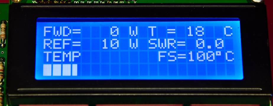
The temperature mode
Now the bar graph displays the temperature. Note that the full scale temperature is fixed to 100 degrees. In this mode you can watch the temperature rise of your PA.
#3. This button is the the “full scale power button” It will display the full scale power of the bar graph on the third line to the right. With this button you can scale down (ONLY DOWN) It will automatically scale up when you reach the limit of the bar graph. So when you produce 105W it will go to the 200W full scale position. If you lower your power to say 90W you will have to scale it manually down to 100W full scale.
The 2 leds display alarm for SWR and temp. They will light in case of high SWR or temperature. The display with show a warning also. This warning will only go away by resetting the PWR SWR meter with the reset button. If for example the temperature has not gone down it will produce immediately another alarm. If the level has gone down below the alarm level, it will work again as a protection circuit.
In case of an alarm Pin #3 of theP10 connector will go high as well, you will have to put a 560 Ohm resistor in series with this pin. (It will be on the board for the next version). For now it is not short circuit protected! This alarm pin can switch off your amp or transceiver PTT or whatever. So whenever there is something wrong with your amplifier or your antenna it will automatically switch your station to standby preventing further damage.
The blower control is on Connector P11 pin #3. You need to insert few more components to get a blower running, see schematic. The temperature where the blower will start running and for what percentage is set in the software. This will vary for different blowers. In fact it is a PWM control.
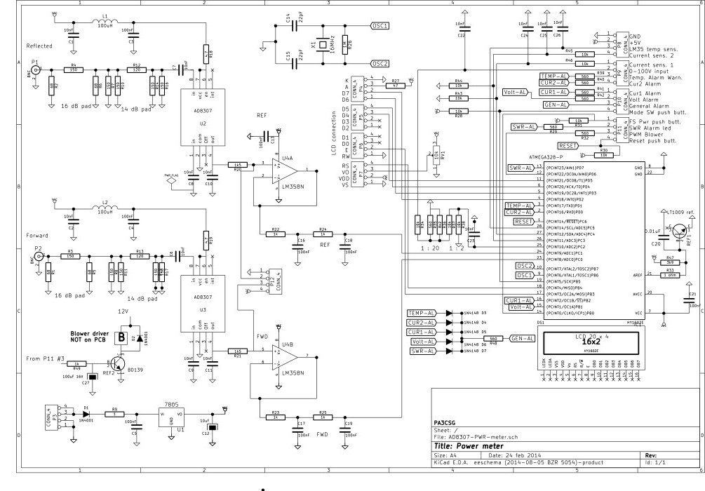
Schematic and board
Below is the schematic of the PWR-SWR meter and protection. It is rather small but you can download a PDF AD8307-PWR-meter
In Europe most hams have some amount of grey hair. This is clearly visible on the flea market 🙂
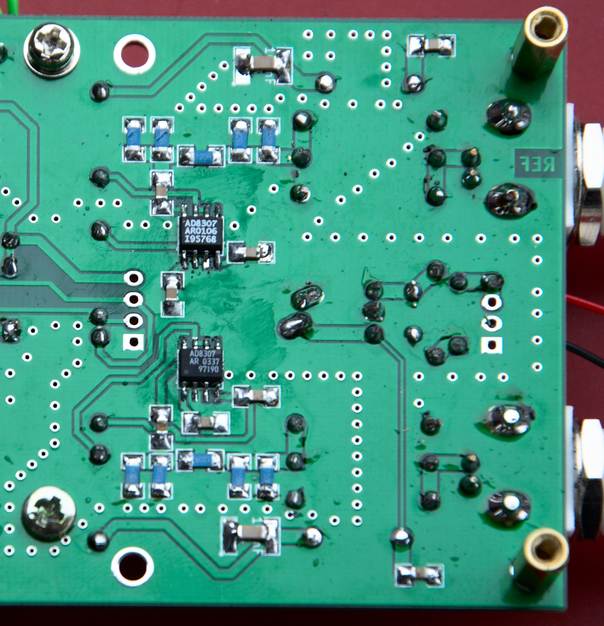
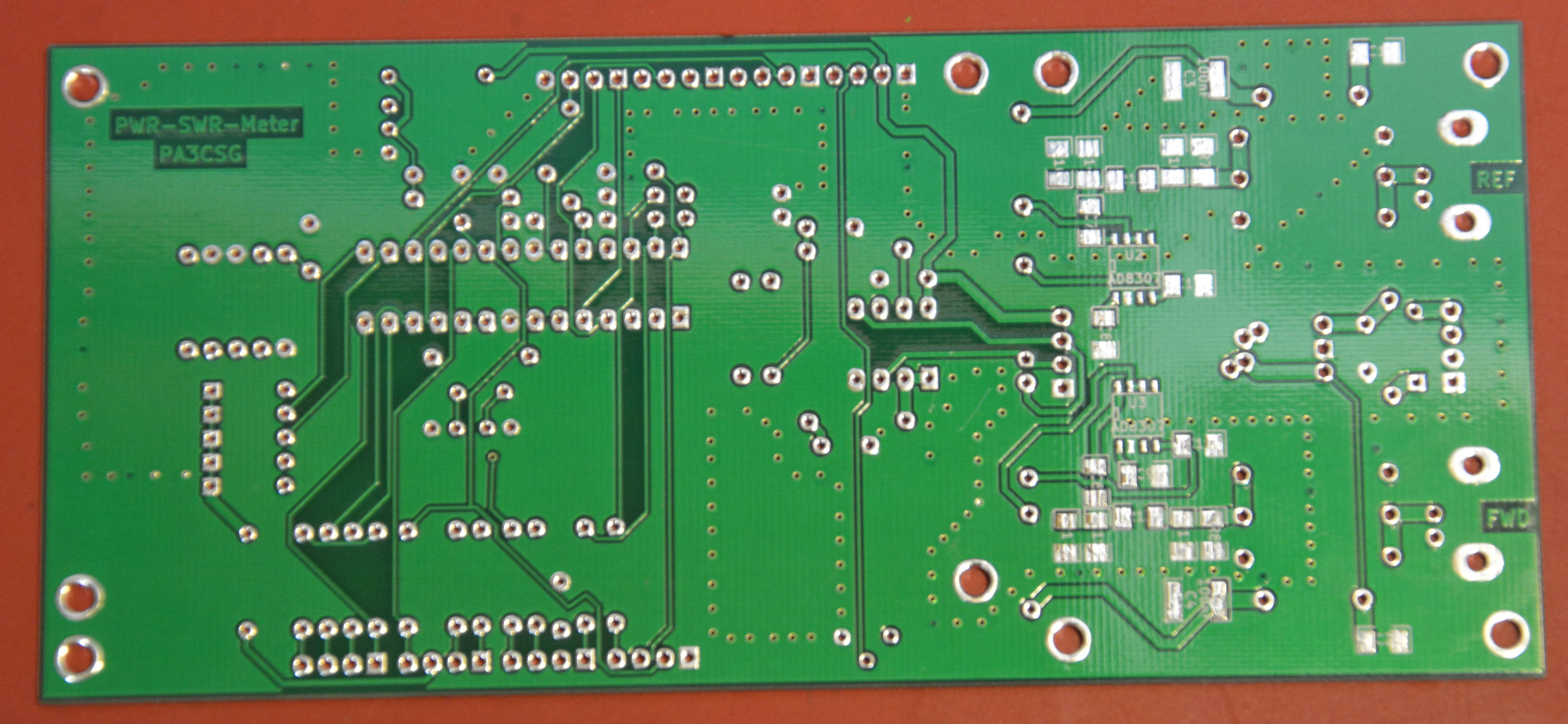
For this reason I decided that the board had to be lumped components. But prices of the AD8307 made me decide different. For a DIL8 $15 was normal price, for the SMD version it was only $3 (prices January 2015). The AD8307 in SMD is not very small so with fine solder point and some 0.4mm solder wire it should be possible. Attenuator network was also done in SMD1206 components (except the 2W resistors).
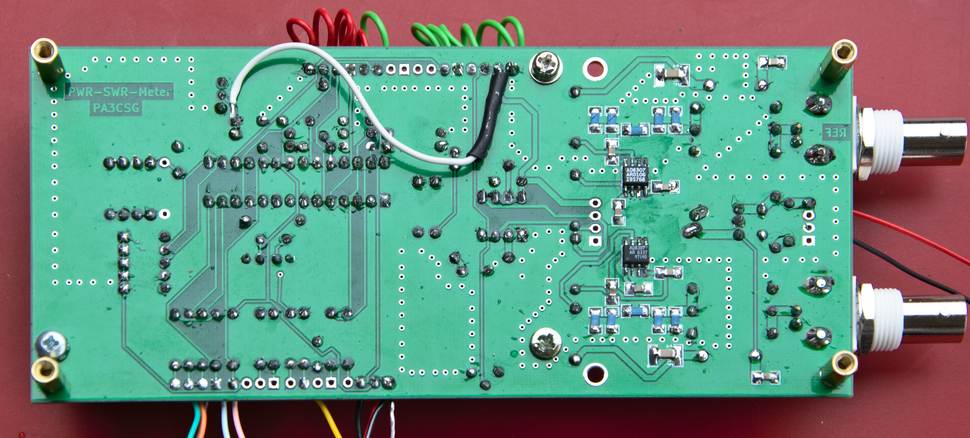
Below is a close up of the SMD section
The LCD display can be mounted on the top of the board. But you can also make the wires a bit longer and mount it in a different way.
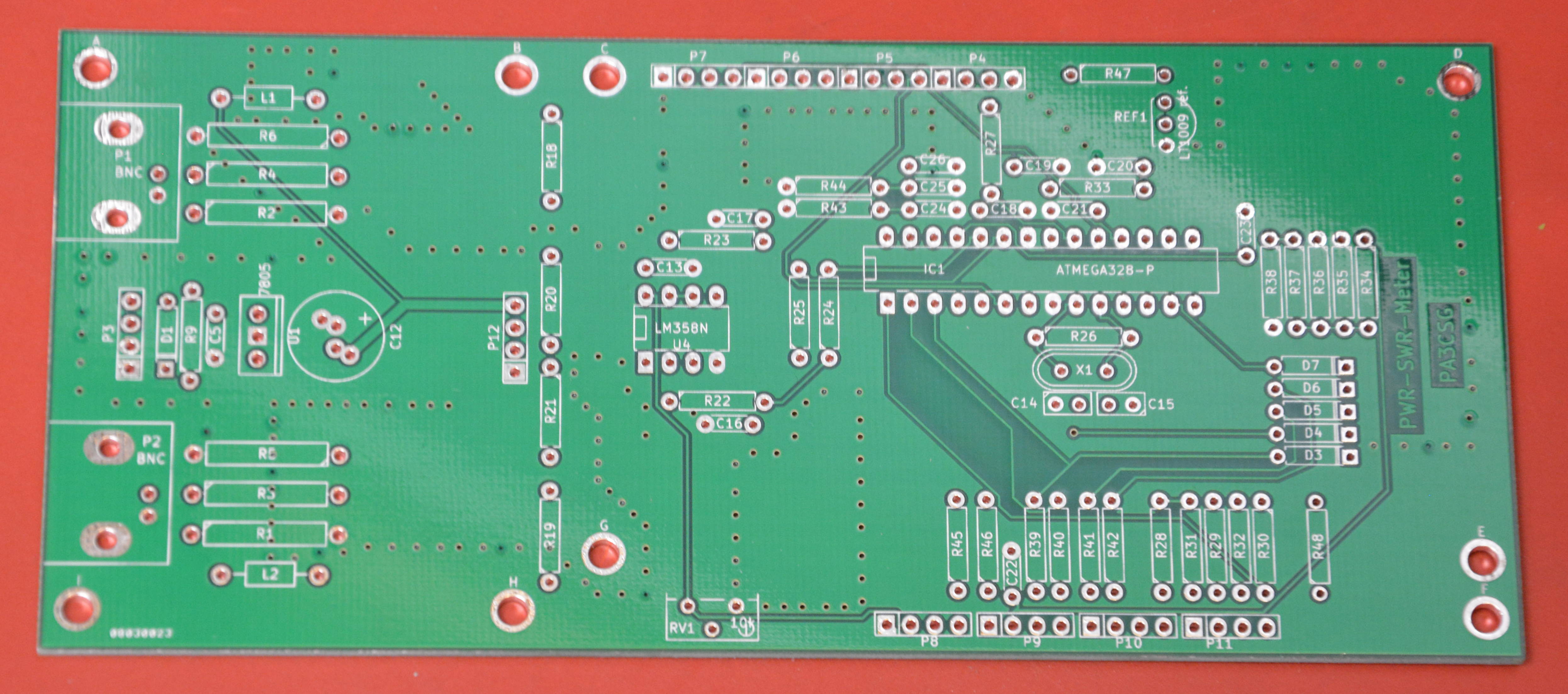
The top view of the board:
Left of the LCD display there are 2 holes. In combination with the left mounting holes a small board with an AD8313 and a small software adaptation the Power SWR meter will be usable up to 2.5 GHz including the 432, 1296 and 2320 MHz frequencies.
The Power SWR meter works very well in combination with the couplers published on the page.
A high power version can be found RF-engineering section, this will work up to 30 MHz
A slightly different version will handle 1kW but will go from 1.5 to 70 MHz. Or from 1.5 to 80 MHz.
There is not much test equipment needed. A DVM should do the job. If you have excess to a signal generator that would make things more accurate.
Please find the code below! Note that I am not a professional programmer and not even a skilled programmer. If you discover any bugs errors or make improvements please let me know!
/* Copyright Geert Stams PA3CSG All trademarks referred to in source code and documentation are copyright their respective owners. This program is free software: you can redistribute it and/or modify it under the terms of the GNU General Public License as published by the Free Software Foundation, either version 3 of the License, or (at your option) any later version. This program is distributed in the hope that it will be useful, but WITHOUT ANY WARRANTY; without even the implied warranty of MERCHANTABILITY or FITNESS FOR A PARTICULAR PURPOSE. See the GNU General Public License for more details. You should have received a copy of the GNU General Public License along with this program. If not, see <http://www.gnu.org/licenses/>. ************************************************************************ PWR SWR meter & TEMP PA protection + Blower PWM Control PA3CSG January 2015 V1.0 ***********************CHANGELOG**************************************** 14 april 2015 added second measurement you can choose one of two measurements 20 april 2015 added low level limits for power, noiselevel of ad8307 might cause swr alarm ************************************************************************ */// include the library code:#include <LiquidCrystal.h>#include <EEPROM.h>#include <LcdBarGraph.h>// initialize the library with the numbers of the interface pinsLiquidCrystal lcd(12, 11, 5, 4, 3, 2);// -- creating bargraph instance, format is (&lcd, lcdNumCols, start X, start Y). So (&lcd, 16, 0, 1) would set the bargraph length to 16 columns and start the bargraph at column 0 on row 1.LcdBarGraph lbg(&lcd, 20, 0, 3); // variables for input pin and control LED //variables for the power meter // For the AD converters int analogInputFWD = 0; //input FWD voltage on pin A0 int analogInputREF = 1; //input REF voltage on pin A1 int analogInputTemp = 5; //input from LM35 temp sensor //For the alarms int alarmswr = 7; //SWR alarm on pin 7 int alarmtemp = 1; //Temp warning on pin 1 //For the blower control int fan = 6; // the pin where fan is int tempMin = 25; // the temperature to start the fan int tempMax = 50; // the maximum temperature when fan is at 100% int fanSpeed; int eff; //float variables float vout2 = 0.0; float vin2 = 0.0; float vout3 = 0.0; float vin3 = 0.0; float out2dbm = 0.0; float out3dbm = 0.0; float RL = 0.0; float coupFWD = 60.4; //coupling factor and attenuators value set before ad8307 mW meter input in dB for FWD float coupREF = 60.4; //coupling factor and attenuators value set before ad8307 mW meter input in dB for REF float wattfwd = 0.0; float wattref = 0.0; float swr = 0.0; float temp = 0.0; // variable to store the value int counterPwr = EEPROM.read(0); int counteroldPwr = counterPwr; int counterMode = 0; int counteroldMode = counterMode; int value2 = 0; int value3 = 0; int value2a = 0; int value3a = 0; int updater = 0; int incrementStatePwr = 0; //will read increment for Power button int lastIncrementStatePwr = 0; int incrementStateMode = 0; //will read increment for Mode button int lastIncrementStateMode = 0; byte incrementButtonPwr = 8; // the pin that the pushbutton for the power selection is attached to byte incrementButtonMode = 13; // the pin that the pushbutton for the power selection is attached to void setup(){ // declaration of pin modes analogReference(EXTERNAL); //sets reference to external connected reference 2,5V LT1009 reference // For the AD converters pinMode (analogInputFWD, INPUT); //input from AD8307 pinMode (analogInputREF, INPUT); //input from AD8307 pinMode (analogInputTemp, INPUT); //input from temp sensor LM35 //For the pussh buttons pinMode(incrementButtonPwr, INPUT); // initialize the button pin for the Pwr switch as an input: pinMode(incrementButtonMode, INPUT); // initialize the button pin for the Mode switch as an input://for the leds outputs pinMode (alarmswr, OUTPUT); //SWR alarm on pin 7 pinMode (alarmtemp, OUTPUT); //Temp warning on pin 1 //setup alarms digitalWrite(alarmswr, LOW); digitalWrite(alarmtemp, LOW); //for the PWM control of the blower pinMode(fan, OUTPUT); // set up the LCD's number of columns and rows: lcd.begin(20, 4); // A little bit of PR lcd.setCursor(0,0); lcd.print("SWR-PWR & protection"); lcd.setCursor(7,1); lcd.print("PA3CSG"); lcd.setCursor(6,2); lcd.print("Welcome"); lcd.setCursor(5,3); lcd.print("Have fun!"); delay(1000); lcd.clear(); //print things on the lcd that donnot change anymore //first line lcd.setCursor(0, 0); lcd.print("FWD="); lcd.setCursor(9, 0); lcd.print("W"); lcd.setCursor(11, 0); lcd.print("T ="); lcd.setCursor(18, 0); lcd.print((char)223); lcd.print("C"); //second line lcd.setCursor(0, 1); lcd.print("REF="); lcd.setCursor(9, 1); lcd.print("W"); lcd.setCursor(11,1); lcd.print("SWR="); //third line is done later //fourth line is bargraph} // main calculation routine starts herevoid loop() { //code for the Power SWR meter // resets value 2 & 3 value2 = 0; value3 = 0; // read the value on analog input 15 times and determine max value for(int i = 0; i <=15; i++) { value2a = analogRead(analogInputFWD); value3a = analogRead(analogInputREF); value2 = max(value2a , value2); value3 = max(value3a , value3); delay(5); } vout2 = (value2 * 2.5) / 1024.0; //FWD vout3 = (value3 * 2.5) / 1024.0; //REF //Conversion to DBM the 0.1851 is the output voltage from the AD8307 with -20dbm applied to the input of the chip. //This means that with the 30 dB attenuators on the PCB you have to apply +10dBm at the input BNC connector. //This voltage seems to be more or less the same for most AD8307 if you have no means of measuring leave it like this. //For the FWD measurement if (vout2 >= 1.851) { out2dbm = ((vout2 - 1.851) / 0.025); out2dbm = (-20 + out2dbm); } if (vout2 < 1.851) { out2dbm = ((1.851 - vout2) / 0.025); out2dbm = (-20 - out2dbm); } //For the REF measurement if (vout3 < 1.855) { out3dbm = ((1.855 - vout3) / 0.025); out3dbm = (-20 - out3dbm); } if (vout3 >= 1.855) { out3dbm = ((vout3 - 1.855) / 0.025); out3dbm = (-20 + out3dbm); } out2dbm = (out2dbm + coupFWD); //FWD out3dbm = (out3dbm + coupREF); //REF /* //converts the reading to dbm out2dbm = vout2-0.830; //set output of ad8307 to 0,830V with -60dbm (at input ad8307) applied FWD out3dbm = vout3-0.830; //set output of ad8307 to 0,830V with -60dbm (at input ad8307) applied REF out2dbm = (out2dbm/0.025)-60+coupFWD; //FWD out3dbm = (out3dbm/0.025)-60+coupREF; //REF */ //calculates return loss and sets limit to 0 RL = out2dbm-out3dbm; if (RL < 2) { RL=0; } //sets level for the SWR protection and turns a led on pin 7 on for alarm //if RL <10 (SWR 1 : 2) the led will light if (out2dbm <=20 && out3dbm <= 20) { RL = 0; } //sets level for the SWR protection and turns a led on pin 7 on for alarm //if RL <10 (SWR 1 : 2) the led will light if (RL < 10) if (RL > 2) { digitalWrite(alarmswr, HIGH); // If used to switch off a solid state PA or similar uncomment the lines below. //lcd.clear(); //lcd.setCursor(4,0); //lcd.print("***ALARM***"); //lcd.setCursor(3,2); //lcd.print("*****SWR*****"); //while(1) { } //endless loop to stop } //calculates Pfwd in watts float wattfwd = pow(10 , (out2dbm/10)); wattfwd = wattfwd/1000; //calculates Pref in watts float wattref = pow(10 , (out3dbm/10)); wattref = wattref/1000; //Reading and counting the button for Pwr incrementStatePwr = digitalRead(incrementButtonPwr); //read the increment button state if(incrementStatePwr != lastIncrementStatePwr) //compare increment button state to its last state { if(incrementStatePwr == LOW)//increment button is pressed { counterPwr = counterPwr + 1; //increment the counter delay(10); //debounce delay } } lastIncrementStatePwr = incrementStatePwr; //Reading and counting the button for Mode incrementStateMode = digitalRead(incrementButtonMode); //read the increment button state if(incrementStateMode != lastIncrementStateMode) //compare increment button state to its last state { if(incrementStateMode == LOW)//increment button is pressed { counterMode = counterMode + 1; //increment the counter delay(10); //debounce delay } } lastIncrementStateMode = incrementStateMode; //limits the the counterPwr to 9 counts and resets to 0 if(counterPwr > 8) { counterPwr = 0; } //limits the the counterMode to 6 counts and resets to 0 if(counterMode > 2) { counterMode = 0; } //routine to semi automatically set the FS level of the wattmeter for fwd pwr in countermode 0. It will scale up but NOT down if (counterMode == 0) { if (wattfwd > 10 ) if (counterPwr ==8){ counterPwr = 7; } if (wattfwd > 20 ) if (counterPwr ==7){ counterPwr = 6; } if (wattfwd > 50 ) if (counterPwr ==6){ counterPwr = 5; } if (wattfwd > 100 ) if (counterPwr ==5){ counterPwr = 4; } if (wattfwd > 200 ) if (counterPwr ==4){ counterPwr= 3; } if (wattfwd > 500 ) if (counterPwr ==3){ counterPwr = 2; } if (wattfwd > 1000 ) if (counterPwr ==2){ counterPwr = 1; } if (wattfwd > 2000 ) if (counterPwr ==1){ counterPwr = 0; } } //routine to semi automatically set the FS level of the wattmeter for ref pwr in countermode 1. It will scale up but NOT down if (counterMode == 1) { if (wattref > 10 ) if (counterPwr ==8){ counterPwr = 7; } if (wattref > 20 ) if (counterPwr ==7){ counterPwr = 6; } if (wattref > 50 ) if (counterPwr ==6){ counterPwr = 5; } if (wattref > 100 ) if (counterPwr ==5){ counterPwr = 4; } if (wattref > 200 ) if (counterPwr ==4){ counterPwr= 3; } if (wattref > 500 ) if (counterPwr ==3){ counterPwr = 2; } if (wattref > 1000 ) if (counterPwr ==2){ counterPwr = 1; } if (wattref > 2000 ) if (counterPwr ==1){ counterPwr = 0; } } //routine to calculate SWR float swr = (1 + sqrt(wattref/wattfwd))/(1 - sqrt(wattref/wattfwd)); swr = constrain(swr, 0, 20); if(wattfwd <= 1) { swr = 0; } //code to read and calculate temp. from sensor temp = analogRead(analogInputTemp); temp = (temp / 4.096); delay (5); //routine for the blower PWM control if(temp < tempMin) { // if temp is lower than minimum temp fanSpeed = 0; // fan is not spinning digitalWrite(fan, LOW); } if((temp >= tempMin) && (temp <= tempMax)) { // if temperature is higher than minimum temp fanSpeed = map(temp, tempMin, tempMax, 50, 255); // the actual speed of fan, set //values so that fan actually starts spinning analogWrite(fan, fanSpeed); // spin the fan at the fanSpeed speed } //sets level for the alarmtemp. protection if (temp > 45) { digitalWrite (alarmtemp, HIGH); //lcd.clear(); //lcd.setCursor(4,0); //lcd.print("***ALARM***"); //lcd.setCursor(2,2); //lcd.print("***TEMPERATURE***"); //while(1) { } //endless loop to stop } // print calculated results to lcd display // first line of the display //clears the space were the fwd power is printed lcd.setCursor(4,0); lcd.print(" "); // small routine to place power on the correct place on the lcd if (wattfwd > 1000) { lcd.setCursor(4,0); } if (wattfwd < 1000) { lcd.setCursor(5,0); } if (wattfwd < 100) { lcd.setCursor(6,0); } if (wattfwd < 10) { lcd.setCursor(7,0); } lcd.print(wattfwd, 0); //clears the space were the temp is printed lcd.setCursor(15, 0); lcd.print(" "); lcd.setCursor(15, 0); lcd.print(temp, 0); //second line of the display //clears the space were the ref power is printed lcd.setCursor(4,1); lcd.print(" "); // small routine to print the REF power on the correct spot if (wattref < 5000) { lcd.setCursor(4,1); } if (wattref < 1000) { lcd.setCursor(5,1); } if (wattref < 100) { lcd.setCursor(6,1); } if (wattref < 10) { lcd.setCursor(7,1); } lcd.print(wattref, 0); //clears the space were the swr is printed lcd.setCursor(16,1); lcd.print(" "); lcd.setCursor(16,1); lcd.print(swr , 1); //third line of the display //small routine to print the FS power of the bargraph on the third line of the display. //This FS power is the same for the Fwd power bargraph. if (counterPwr == 0 ) { lcd.setCursor(14,2); lcd.print(" "); lcd.setCursor(15,2); lcd.print("5000"); } if (counterPwr == 1 ) { lcd.setCursor(14,2); lcd.print(" "); lcd.setCursor(15,2); lcd.print("2000"); } if (counterPwr == 2 ) { lcd.setCursor(15,2); lcd.print("1000"); } if (counterPwr == 3 ) { lcd.setCursor(15,2); lcd.print(" "); lcd.setCursor(16,2); lcd.print("500"); } if (counterPwr == 4 ) { lcd.setCursor(15,2); lcd.print(" "); lcd.setCursor(16,2); lcd.print("200"); } if (counterPwr == 5 ) { lcd.setCursor(15,2); lcd.print(" "); lcd.setCursor(16,2); lcd.print("100"); } if (counterPwr == 6 ) { lcd.setCursor(15,2); lcd.print(" "); lcd.setCursor(17,2); lcd.print("50"); } if (counterPwr == 7 ) { lcd.setCursor(15,2); lcd.print(" "); lcd.setCursor(17,2); lcd.print("20"); } if (counterPwr == 8 ) { lcd.setCursor(15,2); lcd.print(" "); lcd.setCursor(17,2); lcd.print("10"); } //lcd.setCursor(0, 2); //lcd.print(" "); //lcd.setCursor(0, 2); if (counterMode == 0 ) { lcd.setCursor(0, 2); lcd.print(" "); lcd.setCursor(0, 2); lcd.print("FWD"); lcd.setCursor(8, 2); lcd.print(" "); lcd.setCursor(8, 2); lcd.print("FS PWR="); lcd.setCursor(19, 2); lcd.print("W"); } if (counterMode == 1 ) { lcd.setCursor(0, 2); lcd.print(" "); lcd.setCursor(0, 2); lcd.print("REF"); lcd.setCursor(8, 2); lcd.print(" "); lcd.setCursor(8, 2); lcd.print("FS PWR="); lcd.setCursor(19, 2); lcd.print("W"); } if (counterMode == 2 ) { lcd.setCursor(0, 2); lcd.print(" "); lcd.setCursor(0, 2); lcd.print("TEMP"); lcd.setCursor(12, 2); lcd.print("FS=100"); lcd.setCursor(18, 2); lcd.print((char)223); lcd.setCursor(19, 2); lcd.print("C"); } /* if (counterMode == 0) { if (counteroldMode == 6); { lcd.setCursor(0, 3); lcd.print(" "); } */ //fourth line of the display counterMode sets the function of the fourth line // following prints graph bar counterMode = 0 This is FWD Mode lcd.setCursor(0,3); if (counterMode == 0) { if (counterPwr == 0 ) { lbg.drawValue( wattfwd, 5000); // -- draw bar graph from the analog value readed delay(1); } if (counterPwr == 1 ) { lbg.drawValue( wattfwd, 2000); // -- draw bar graph from the analog value readed delay(1); } if (counterPwr == 2 ) { lbg.drawValue( wattfwd, 1000); // -- draw bar graph from the analog value readed delay(1); } if (counterPwr == 3 ) { lbg.drawValue( wattfwd, 500); // -- draw bar graph from the analog value readed delay(1); } if (counterPwr == 4 ) { lbg.drawValue( wattfwd, 200); // -- draw bar graph from the analog value readed delay(1); } if (counterPwr == 5 ) { lbg.drawValue( wattfwd, 100); // -- draw bar graph from the analog value readed delay(1); } if (counterPwr == 6 ) { lbg.drawValue( wattfwd, 50); // -- draw bar graph from the analog value readed delay(1); } if (counterPwr == 7 ) { lbg.drawValue( wattfwd, 20); // -- draw bar graph from the analog value readed delay(1); } if (counterPwr == 8 ) { lbg.drawValue( wattfwd, 10); // -- draw bar graph from the analog value readed delay(1); } } // following prints graph bar counterMode = 1 This is REF Mode if (counterMode == 1) { lcd.setCursor(0,3); if (counterPwr == 0 ) { lbg.drawValue( wattref, 5000); // -- draw bar graph from the analog value readed delay(1); } if (counterPwr == 1 ) { lbg.drawValue( wattref, 2000); // -- draw bar graph from the analog value readed delay(1); } if (counterPwr == 2 ) { lbg.drawValue( wattref, 1000); // -- draw bar graph from the analog value readed delay(1); } if (counterPwr == 3 ) { lbg.drawValue( wattref, 500); // -- draw bar graph from the analog value readed delay(1); } if (counterPwr == 4 ) { lbg.drawValue( wattref, 200); // -- draw bar graph from the analog value readed delay(1); } if (counterPwr == 5 ) { lbg.drawValue( wattref, 100); // -- draw bar graph from the analog value readed delay(1); } if (counterPwr == 6 ) { lbg.drawValue( wattref, 50); // -- draw bar graph from the analog value readed delay(1); } if (counterPwr == 7 ) { lbg.drawValue( wattref, 20); // -- draw bar graph from the analog value readed delay(1); } if (counterPwr == 8 ) { lbg.drawValue( wattref, 10); // -- draw bar graph from the analog value readed delay(1); } } // following prints graph bar counterMode = 2 This is Temperature Mode if (counterMode == 2) { lcd.setCursor(0,3); lbg.drawValue( temp, 100); // -- draw bar graph from the analog value readed delay(1); }; //saves the counterPwr value in the eeprom for the next time so that you don't have to set the FS power every time. if (counterPwr != counteroldPwr) { EEPROM.write(0,counterPwr); } // sleep... delay(30); }Below is a picture of the unit build by Dave G4RGK