When looking for a new transceiver from HF up 50 & 70 MHz I was disappointed by the antenna outputs, just ONE, better ONLY ONE. Another thing missing was a separate RX antenna input for the low HF bands. Some digging on the internet brought up a nice idea from DJ0IP (HERE) for a separate RX antenna input It looked easy to combine with the multiple antenna outputs I needed. I needed 5 and one spare. Studying the antenna switches on the internet showed that effort was done to get good matching on the higher HF bands. Most of them were not specified up to 70MHz so some difficulty was expected.
I came up with the following circuit diagram:
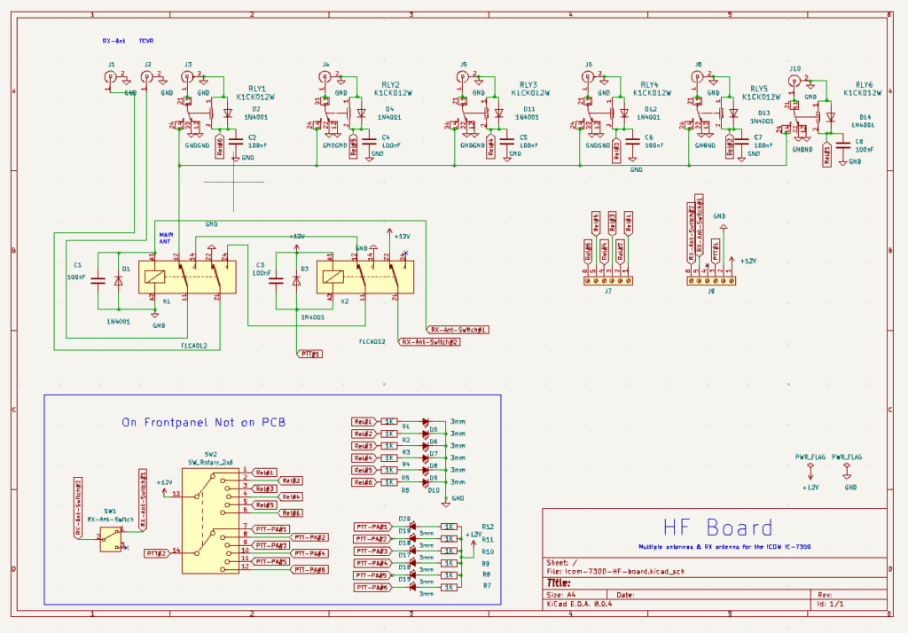
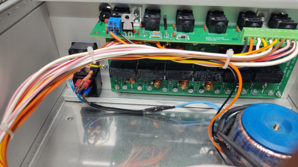
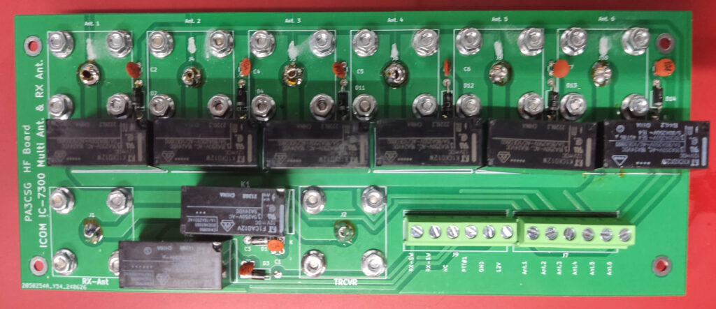
A PCB was designed and the first tries were made. As it was for 100W and the antenna switches not in use were grounded no high isolation was required. Normal relays the K1CK012W were used and for the RX antenna F1CA012 was used.
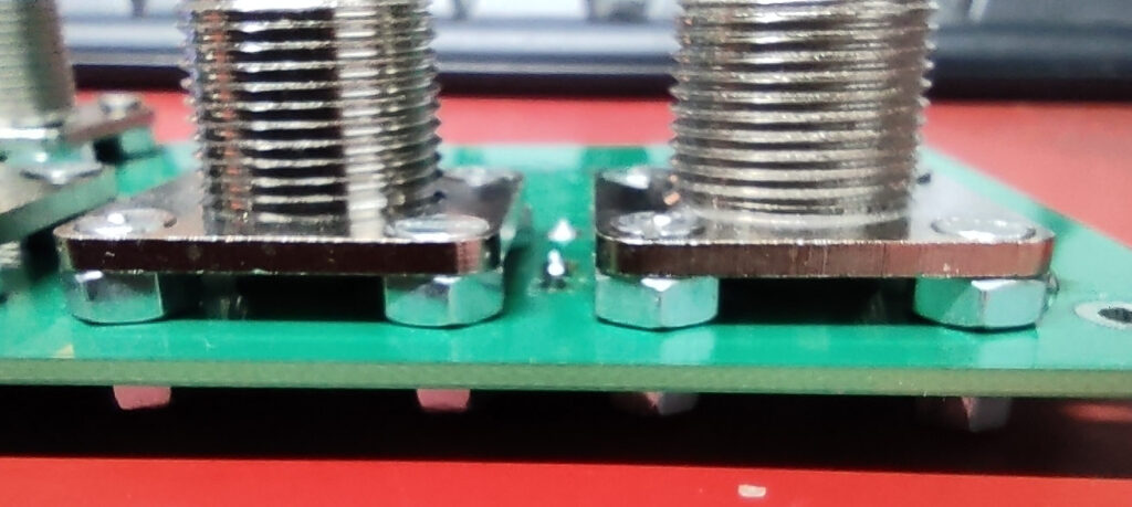
The UHF connectors are mounted with M3 screw with sunken head. Otherwise mounting through the panel might not leave enough of the thread. The diodes and 100nF capacitors across the relays these can be placed on either side.
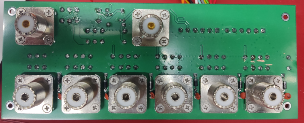
The connectors are mounted a little bit higher that the PCB. Use M4 nuts for that.
The component side of the PCB
Now some measurements:
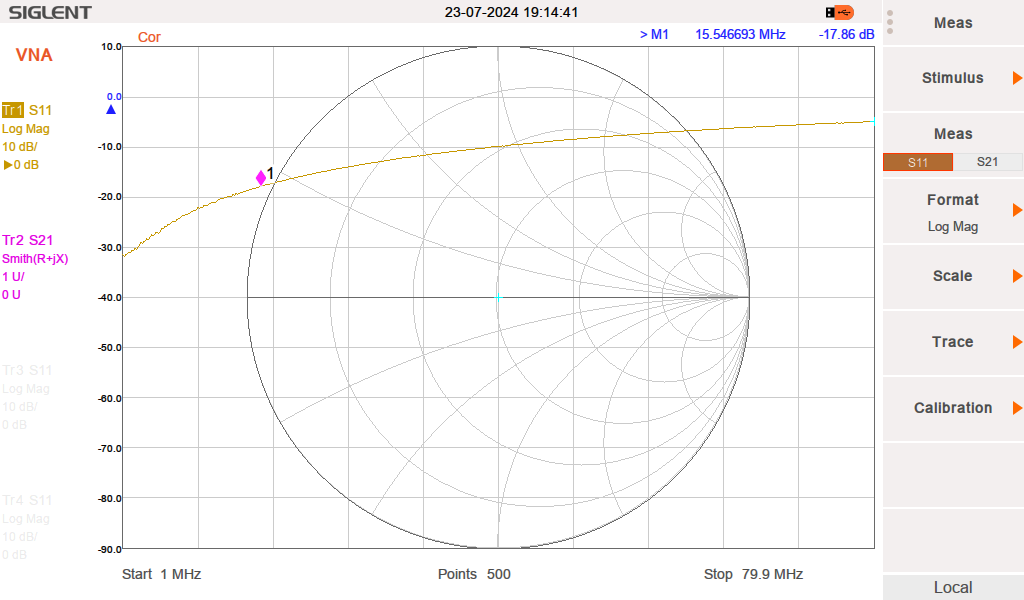
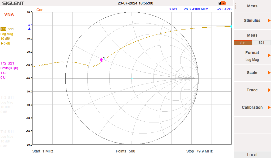
As expected the matching (S11) was not too good on the higher frequencies. Giving a return loss of about 20dB on 14 MHz rising to a few dB’s on 70 MHz. The plot below goes from 1 – 80 MHz. Below a plot of Antenna #2 to the transceiver.
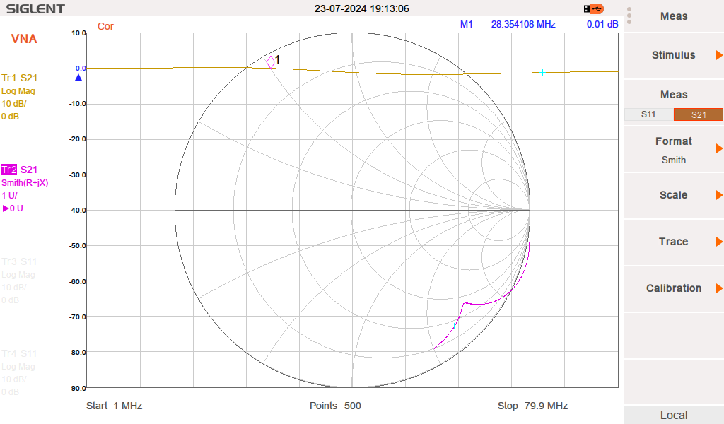
The losses were very acceptable over the same frequency range. Very little losses. Here again antenna # 2.
Some matching had to be done. I measured the complex value of the switch and did some matching. A simple L is series and a C to ground did the job very well.
Analog devices has a nice tool for this HERE
| Frequency | Measured R | Measured J | C Value | L Value | L |
| 28 MHz | 41 | -21J | 51 | 225nH | 7 turns on 8mm 10mm long |
| 50 MHz | 31 | -19J | 47pF | 138nH | 5 turns on 8mm 8mm long |
| 70 MHz | 24 | -13J | 47pFpF | 86nH | 4 turns on 8mm 8mm long |
In the photo below you can see the matching, simply done by milling a few mm away from the copper track. From left to right: 70 MHz – 50 MHz – 28 MHz (and below) – 28 MHz (and below). Some extra tuning can be done by bending the inductors. As capacitors I used the ATC100B these are “hidden” by the relay.
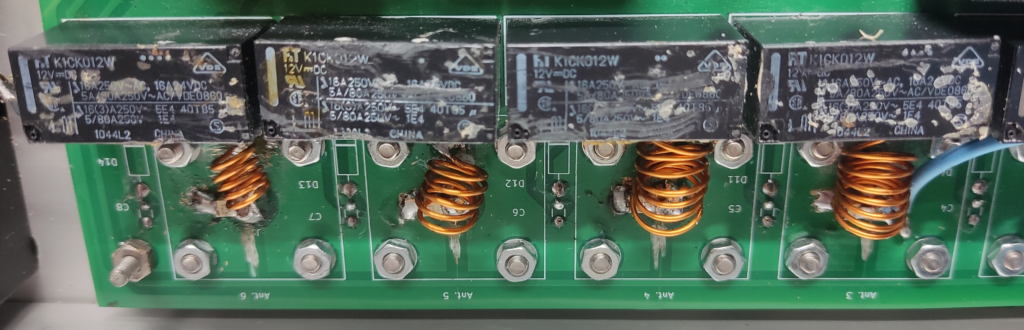
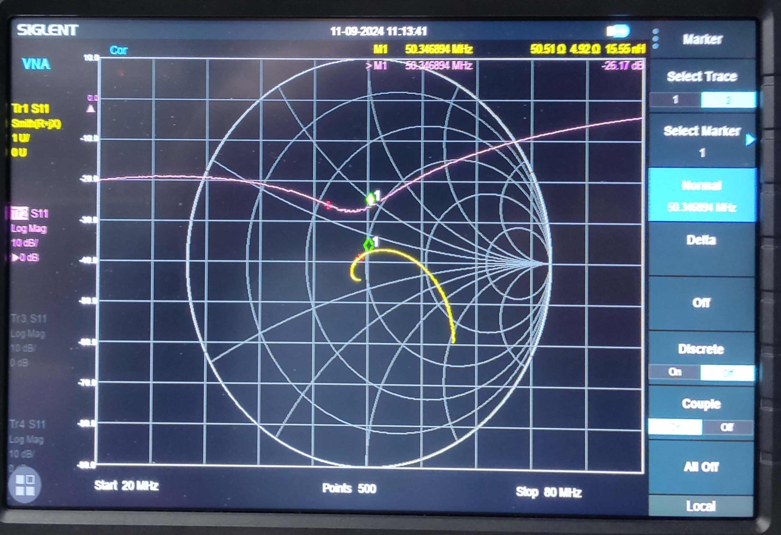
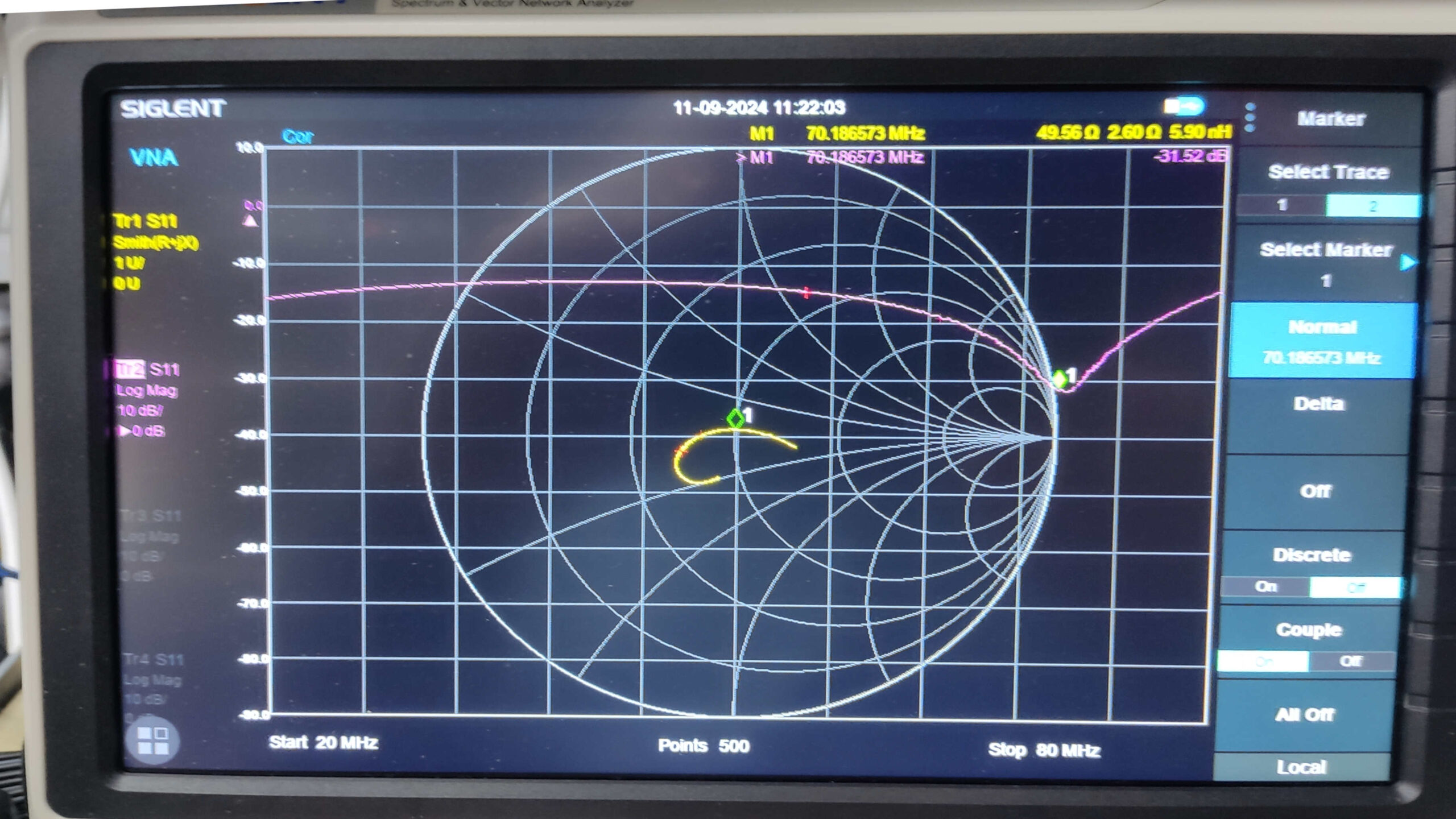
From left to right: 28MHz – 50 MHz – 70 MHz S11 Matching. For a bigger image right click and “open image in new tab”
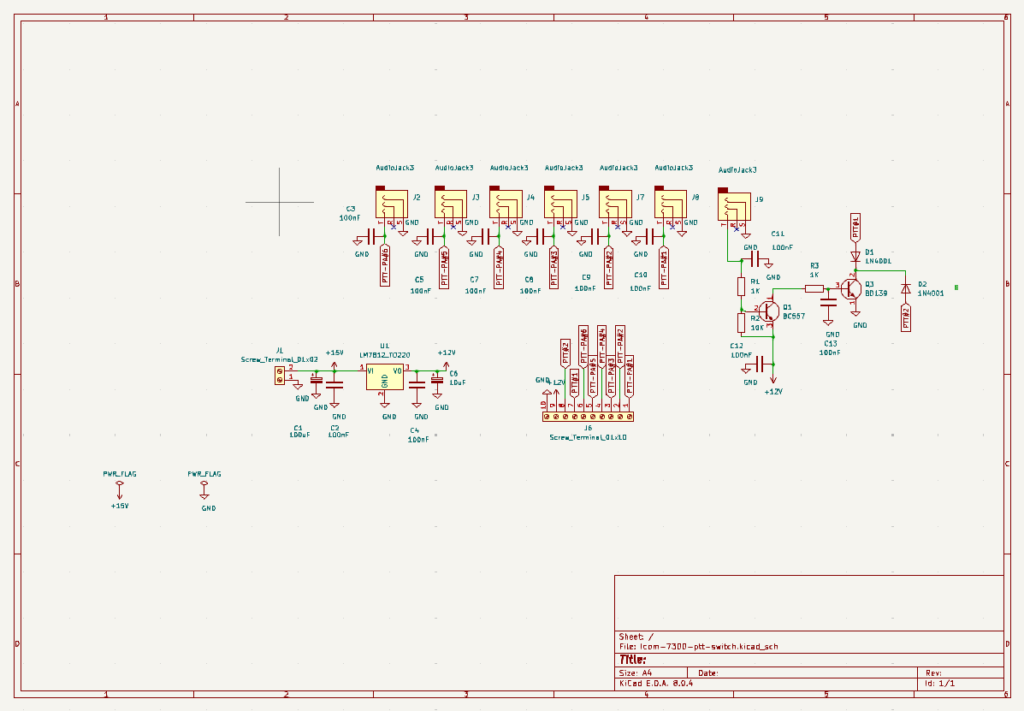
The PTT switching
The following circuit was made on a separate PCB in order to automatically switch the PTT to the amp – transverter or whatever to be switched with the antenna. In the circuit below J9 is the input of the PTT from the transceiver. J9 going to ground will make the collector of Q1 go high and the collector of Q3 will go low, switching the attached gear to transmit. A simple 12V power supply is on this PCB as well.
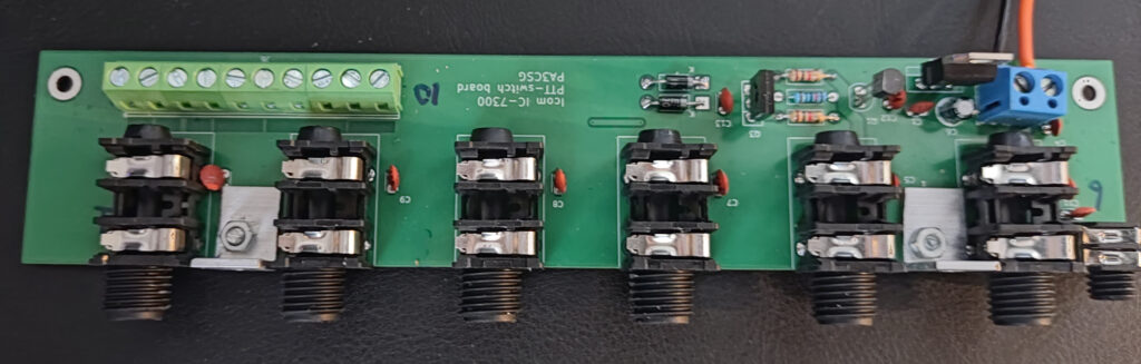
The 6,3mm jacks are Neutrik NR-J4HF and the 3,5mm jack is a Cliff FCR1281. All components should be easy available from Reichelt. Don’t make the same mistake as I did. I forgot to order the nut for the 6,3mm jacks Neutrik NR-JNUTB these are not included.
There is plenty of room in the box to add a band decoder.
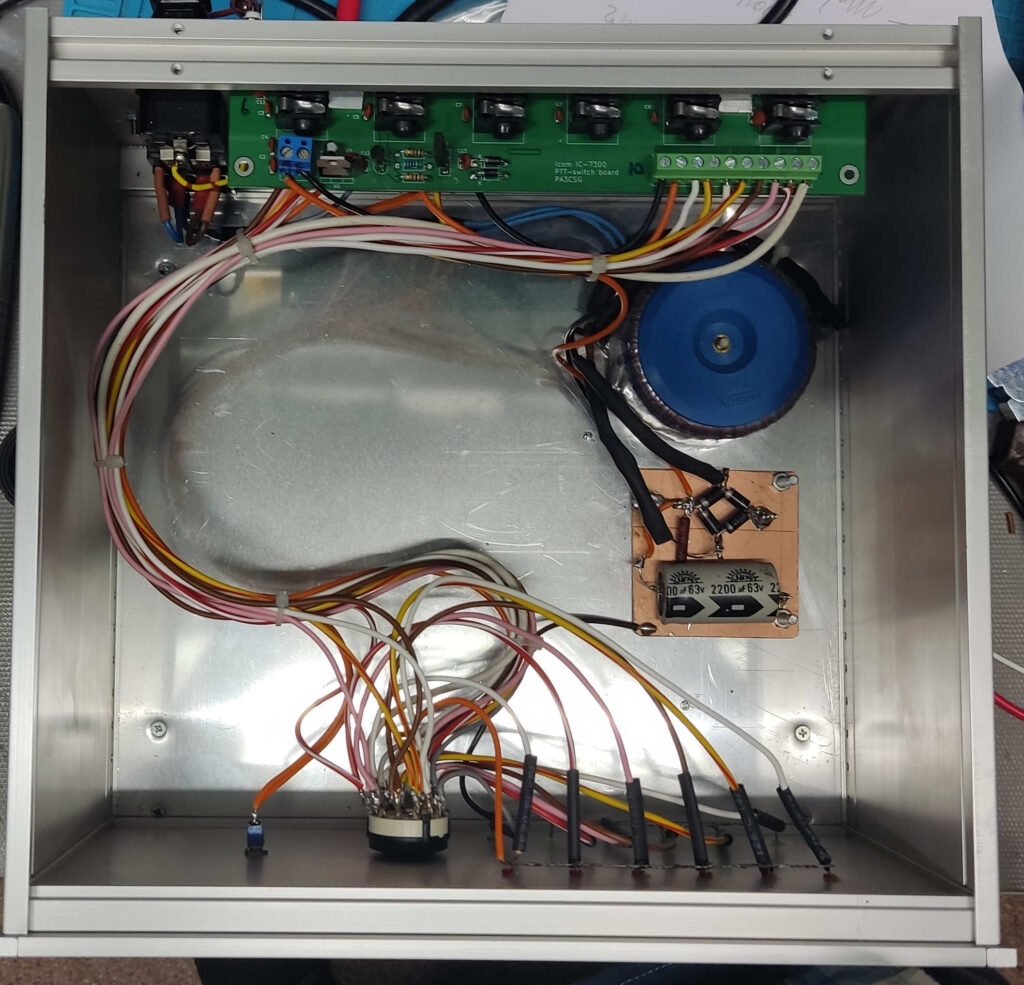
The inside of the finished unit: