
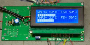
For my 23cm PA consisting of 4 PA’s I needed a temperature meter with protection in case the amplifier gets hot. The system is build on the same board as the power meter. The full scale temperature can be set with a push button.
The code derived from the power / swr meter.
/*
Temperature meter based on the powermeter swrmeter board, connections for
pushbuttons leds etc. remain the same as on the original board
PA3CSG march 2017 V1.0
Code comes without any warranty.
***********************CHANGELOG****************************************
************************************************************************
*/
// include the library code:
#include <LiquidCrystal.h>
#include <EEPROM.h>
#include <LcdBarGraph.h>
// initialize the library with the numbers of the interface pins
LiquidCrystal lcd(12, 11, 5, 4, 3, 2);
// — creating bargraph instance, format is (&lcd, lcdNumCols, start X, start Y). So (&lcd, 16, 0, 1) would set the bargraph length to 16 columns and start the bargraph at column 0 on row 1.
LcdBarGraph lbg0(&lcd, 20, 0, 1);
LcdBarGraph lbg1(&lcd, 20, 0, 3);
// variables for input pin and control LED
//variables for the power meter
// For the AD converters
int analogInputTEMP1 = 0; //input 1st LM35 sensor on pin A0
int analogInputTEMP2 = 1; //input 2nd LM35 sensor on pin A1
//For the alarms
int alarmtemp1 = 7; //Temp1 alarm on pin 7
int alarmtemp2 = 1; //Temp2 alarm on pin 1
//float variables
float TEMP1 = 0.0;
float TEMP2 = 0.0;
// variable to store the value
int counterTemp = EEPROM.read(0);
int counteroldTemp = counterTemp;
int counterMode = 0;
int counteroldMode = counterMode;
//int updater = 0;
int incrementStateTemp = 0; //will read increment for Power button
int lastIncrementStateTemp = 0;
int incrementStateMode = 0; //will read increment for Mode button
int lastIncrementStateMode = 0;
byte incrementButtonTemp = 8; // the pin that the pushbutton for the power selection is attached to
byte incrementButtonMode = 13; // the pin that the pushbutton for the power selection is attached to
void setup() {
// declaration of pin modes
analogReference(EXTERNAL); //sets reference to external connected reference 2,5V LT1009 reference
// For the AD converters
pinMode (analogInputTEMP1, INPUT); //input from LM35
pinMode (analogInputTEMP2, INPUT); //input from LM35
//For the pussh buttons
pinMode(incrementButtonTemp, INPUT); // initialize the button pin for the Pwr switch as an input:
pinMode(incrementButtonMode, INPUT); // initialize the button pin for the Mode switch as an input:
//for the leds outputs
pinMode (alarmtemp1, OUTPUT); //Temp warning on pin 7
pinMode (alarmtemp2, OUTPUT); //Temp alarm on pin 1
//setup alarms
digitalWrite(alarmtemp1, LOW);
digitalWrite(alarmtemp2, LOW);
// set up the LCD’s number of columns and rows:
lcd.begin(20, 4);
// A little bit of PR
lcd.setCursor(0, 0);
lcd.print(” TEMPERATURE METER”);
lcd.setCursor(7, 1);
lcd.print(“PA3CSG”);
lcd.setCursor(6, 2);
lcd.print(“Welcome”);
lcd.setCursor(5, 3);
lcd.print(“Have fun!”);
delay(1500);
lcd.clear();
//print things on the lcd that donnot change anymore
//first line
lcd.setCursor(0, 0);
lcd.print(“AMP3=”);
lcd.setCursor(8, 0);
lcd.print((char)223);
lcd.print(“C”);
lcd.setCursor(12, 0);
lcd.print(“FS= “);
//second line is bargraph
//third line
lcd.setCursor(0, 2);
lcd.print(“AMP4=”);
lcd.setCursor (8, 2);
lcd.print((char)223);
lcd.print(“C”);
lcd.setCursor(12, 2);
lcd.print(“FS= “);
//fourth line is bargraph
}
// main calculation routine starts here
void loop() {
incrementStateTemp = digitalRead(incrementButtonTemp); //read the increment button state
if (incrementStateTemp != lastIncrementStateTemp) //compare increment button state to its last state
{
if (incrementStateTemp == LOW) //increment button is pressed
{
counterTemp = counterTemp + 1; //increment the counter
delay(10); //debounce delay
}
}
lastIncrementStateTemp = incrementStateTemp;
//Reading and counting the button for Mode
incrementStateMode = digitalRead(incrementButtonMode); //read the increment button state
if (incrementStateMode != lastIncrementStateMode) //compare increment button state to its last state
{
if (incrementStateMode == LOW) //increment button is pressed
{
counterMode = counterMode + 1; //increment the counter
delay(10); //debounce delay
}
}
lastIncrementStateMode = incrementStateMode;
//limits the the counterTemp to 3 counts and resets to 0
if (counterTemp > 2)
{
counterTemp = 0;
}
//limits the the counterMode to 1 counts and resets to 0
if (counterMode >= 1)
{
counterMode = 0;
}
//code to read and calculate TEMP1 from sensor
TEMP1 = analogRead(analogInputTEMP1);
TEMP1 = (TEMP1 / 4.096);
delay (5);
//sets level for the alarmtemp.
if (TEMP1 > 55) {
digitalWrite (alarmtemp1, HIGH);
lcd.clear();
lcd.setCursor(4, 0);
lcd.print(“***ALARM***”);
lcd.setCursor(2, 2);
lcd.print(“*TEMPERATURE AMP1*”);
while (1) { } //endless loop to stop
}
//code to read and calculate TEMP2 from sensor
TEMP2 = analogRead(analogInputTEMP2);
TEMP2 = (TEMP2 / 4.096);
delay (5);
//sets level for the alarmtemp.
if (TEMP2 > 55) {
digitalWrite (alarmtemp2, HIGH);
lcd.clear();
lcd.setCursor(4, 0);
lcd.print(“***ALARM***”);
lcd.setCursor(2, 2);
lcd.print(“*TEMPERATURE AMP2″);
while (1) { } //endless loop to stop
}
// print calculated results to lcd display
// first line of the display
//clears the space were the temp1 is printed
lcd.setCursor(6, 0);
lcd.print(” “);
lcd.setCursor(6, 0);
lcd.print (TEMP1 , 0);
lcd.setCursor (8, 0);
lcd.print((char)223);
lcd.print(“C”);
//second line of the display this is a bargraph
//third line of the display
//clears the space were the temp2 is printed
lcd.setCursor(6, 2);
lcd.print(” “);
lcd.setCursor(6, 2);
lcd.print (TEMP2 , 0);
lcd.setCursor (8, 2);
lcd.print((char)223);
lcd.print(“C”);
//fourth line of the display this is a bargraph
//small routine to print the FS temperature of the bargraph on the first & third line of the display.
if (counterTemp == 0 )
{
lcd.setCursor(15, 0);
lcd.print(” “);
lcd.setCursor(15, 0);
lcd.print(” 50″);
lcd.setCursor (18, 0);
lcd.print((char)223);
lcd.print(“C”);
}
if (counterTemp == 1 ) {
lcd.setCursor(15, 0);
lcd.print(” “);
lcd.setCursor(15, 0);
lcd.print(“100”);
lcd.setCursor (18, 0);
lcd.print((char)223);
lcd.print(“C”);
}
if (counterTemp == 2 ) {
lcd.setCursor(15, 0);
lcd.print(” “);
lcd.setCursor(15, 0);
lcd.print(“200”);
lcd.setCursor (18, 0);
lcd.print((char)223);
lcd.print(“C”);
}
if (counterTemp == 0 )
{
lcd.setCursor(15, 2);
lcd.print(” “);
lcd.setCursor(15, 2);
lcd.print(” 50″);
lcd.setCursor (18, 2);
lcd.print((char)223);
lcd.print(“C”);
}
if (counterTemp == 1 ) {
lcd.setCursor(15, 2);
lcd.print(” “);
lcd.setCursor(15, 2);
lcd.print(“100”);
lcd.setCursor (18, 2);
lcd.print((char)223);
lcd.print(“C”);
}
if (counterTemp == 2 ) {
lcd.setCursor(15, 2);
lcd.print(” “);
lcd.setCursor(15, 2);
lcd.print(“200”);
lcd.setCursor (18, 2);
lcd.print((char)223);
lcd.print(“C”);
}
//print bargraph on lines 1 & 3
lcd.setCursor(0, 1);
if (counterMode == 0) {
if (counterTemp == 0 ) {
lbg0.drawValue( TEMP1, 50); // — draw bar graph from the analog value readed
delay(1);
}
if (counterTemp == 1 ) {
lbg0.drawValue( TEMP1, 100); // — draw bar graph from the analog value readed
delay(1);
}
if (counterTemp == 2 ) {
lbg0.drawValue( TEMP1, 200); // — draw bar graph from the analog value readed
delay(1);
}
lcd.setCursor(0, 3);
if (counterMode == 0) {
if (counterTemp == 0 ) {
lbg1.drawValue( TEMP2, 50); // — draw bar graph from the analog value readed
delay(1);
}
if (counterTemp == 1 ) {
lbg1.drawValue( TEMP2, 100); // — draw bar graph from the analog value readed
delay(1);
}
if (counterTemp == 2 ) {
lbg1.drawValue( TEMP2, 200); // — draw bar graph from the analog value readed
delay(1);
}
//saves the counterTemp value in the eeprom for the next time so that you don’t have to set the Temp every time.
if (counterTemp != counteroldTemp) {
EEPROM.write(0, counterTemp);
}
}
// sleep…
delay(20);
}
}