The need for coaxrelays for the new 50-70 MHz amplifier led to this design. I had very good experiences with the Fujitsu relay which datasheet can be found HERE
I has been in use in several HF solid state amplifiers as well in sever tube amplifiers for HF. I also run a remote antenna switch with these relays some 50M away in my garden. I never lost a single relay due to burning contacts. It even took the mismatch in the remote antenna switch transmitting on the wrong band.
In a discussion with Wim, PA0WMX, we came up with the idea of using 2 of these relays and match the inductance by adding small capacitors to it. A PCB board was designed and tested. The results are presented here. By adding a second relay a good isolation could be achieved.
The matching is a very important item for solid state amplifiers. A bad matching in a coaxrelay or a filter will result in excessive heat dissipation of the solid state amplifier. Please pay attention.
We came up with the following schematic:
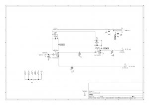
An attempt was made to make the board as universal as possible. Fitting in a 74 x 74 x 50mm standard tin box. But also non shielded operation is possible. The board has room for a series resistor to make it operational on a large range of voltages. The relays can be switched to + or to ground by just changing the connections. Several units were build.
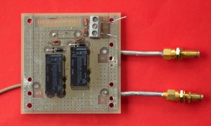
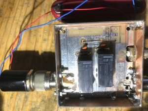
The first unit roughly build in a PCB material box, proved to have very nice values
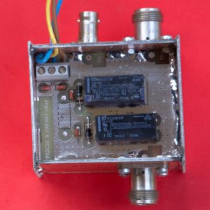
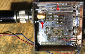
By adding 2 ATC100B capacitors to ground the matching was good. By soldering some 2.5mm coper wire on the PCB tracks the unit was made suitable for high power. Note the yellow wire, it replaces the resistor. This unit is build to operate on 12V direct.
A second unit was build and tested. I was optimised for 50 to 70 MHz. In this form it is not usable for 145MHz!
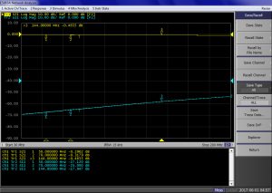
This plot shows the relay from TX to the RX port. Losses with the 2 relays in series are moderate. Around 0.3dB Matching is good around 25dB
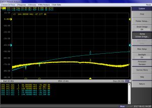
The next plot shows the isolation between the RX and TX port. TX port terminated with 50 Ohms. The relays are energised. Isolation is >65dB
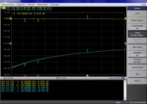
The next plot shows the loss between the TX port and the antenna port, Losses are 0.1dB or below on 50-70 MHz. It is well matched when the TX port is terminated with a 50 Ohm load. PTT is activated.
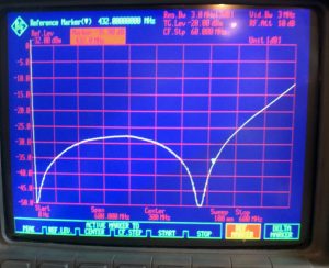
A 432 MHz version!!
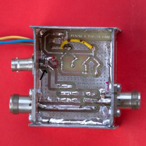
Wim PA0WMX had a go with the coaxrelay board and he tuned it to 432 MHz by two little steps. Some pictures show how he did it
Below his build of the coaxrelay
He added some simple modifications, first a cap was soldered over the connector so that it remains coaxial as long as possible. Second Wim milled some copper away from the line. See the pic below!
The result is seen on the plot below, a S11 (matching) better than 30dB! Wow