The azimuth rotor idea came from a drawing in an old EME newsletter of the K2UYH mount. This drawing is available from the antenna chapter of the Newsletter Collection (on this website) I varied a few things due to the availability of materials.
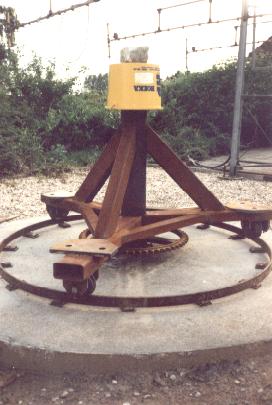
The tower is completely rotating around a 10cm in diameter steel axis. This is not visible on the photo. The drive is 1:3 ratio chain, this will eliminate almost every play on the reduction. A bigger ratio would even be better but is hard to find.
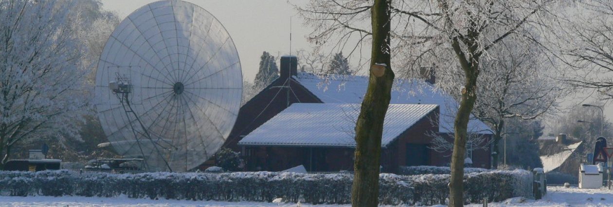
One of the basic ideas constructing this mount was that the feed support should not be mounted on the dish itself. I choose to make a steel bar going around the dish. On the end of this bar the feed support is mounted on 2 simple bearings. A simple winch ( as well mounted on the end of the bar) allows the feed to be wound down. This allows access to the feed from ground level.
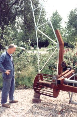
On this photo you can see the central dish hub with one rib mounted. The steel bar pointing upwards is the beginning of the bar going around the dish.
Note that the centre of the hub is above the elevation axis!
When completed the dish would be pointing 90 degrees upwards.
Same picture but in normal position the dish would be pointing towards the horizon.
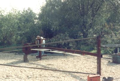
On the left Geert PA3CSG, PA3DWW, Dre, on the right.
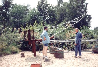
The steel bar is completed now to the rim of the dish. Rectangular steel bar in parallel with mast are used for mounting the counterweights on. In this position the dish would be pointing 90 degrees up.

Same as above only the picture is taken from a different angle.
What was mounted on the tower on last photo is taken off now. The horizontal bar is the bar which goes around the dish.. The vertical bar on the right has 2 bearings on and a winch (not shown). The tubing triangle is the future feed support. Please take a closer look at the dish construction details. Hopefully this will make things a bit clearer.