I broke my plate choke! It was too close to the coolers of the GS35 in the amplifier. The result was a burned choke. I bought it commercially.
A search on the internet did not supply a lot of information. The best info is:
https://www.w8ji.com/rf_plate_choke.htm
The measurement was rather simple and well described. These measurements can be done by everyone. A very good idea!
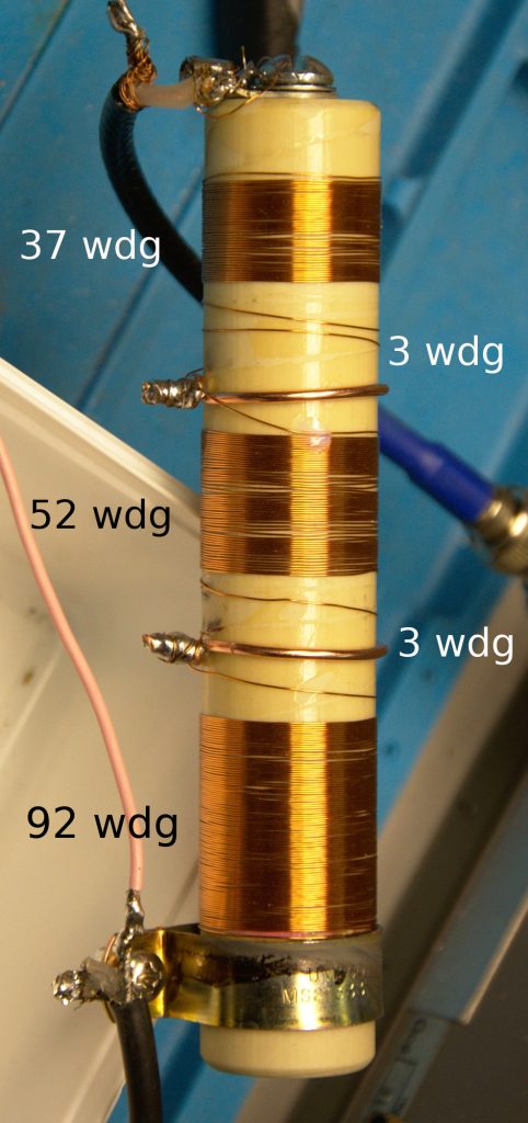
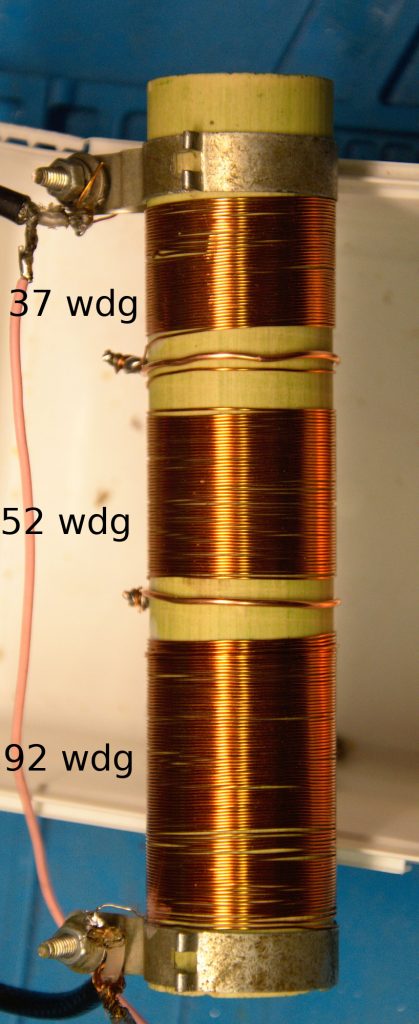
As I had a spectrum analyser and a tracking generator available I decided to use these for the measurements. I rewound the plate choke the damage was so bad it was impossible to tell exact numbers. In the middle I put copper straps to hold the windings and if I would burn it again it would save me from rewinding all. I used 0.35 or 0.4 mm diameter wire. The windings were glued to the ceramic body using small drops of my daughters nail varnish. The ceramic body was 25mm diameter.
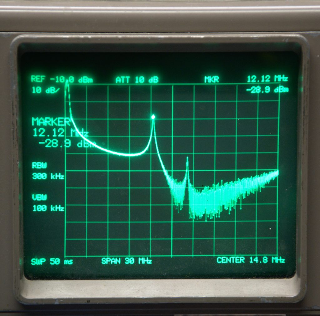
The results were close to W8JI measurements, providing 2 serie-resonant peaks, clearly visible on the spectrum analyser.
I decided to give it another try. I cleaned an old ceramic resistor, removed the wire and the paint on it. It was a 30 mm ceramic tube left over. I decided to stay close to the above design. I wanted to draw some more current so I rewound it using 0.5mm wire. This would increase parasitic capacitances and I recalled that it could be dramatic from my experiments on couplers for the HF bands.
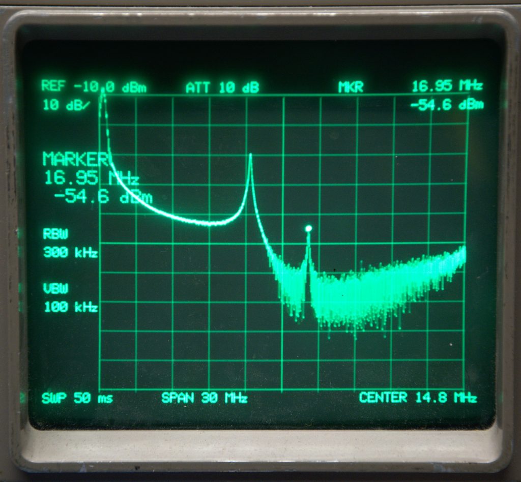
The following pictures show the results: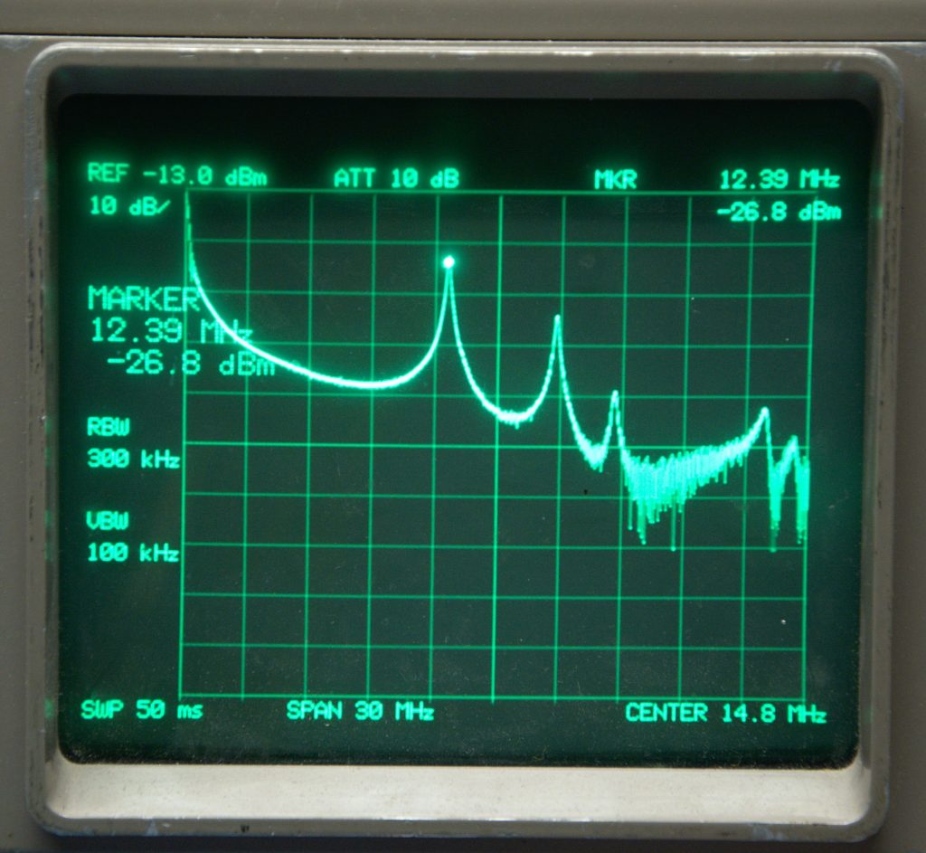
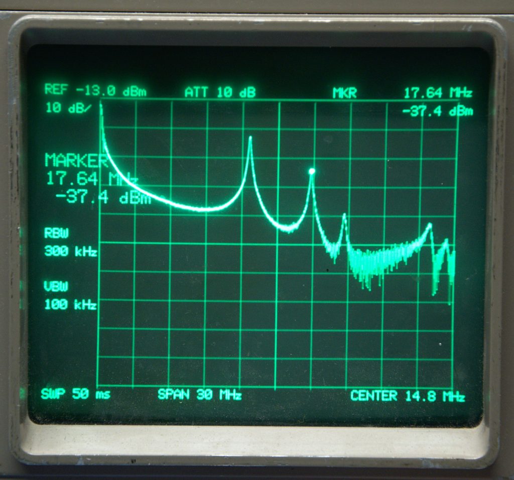
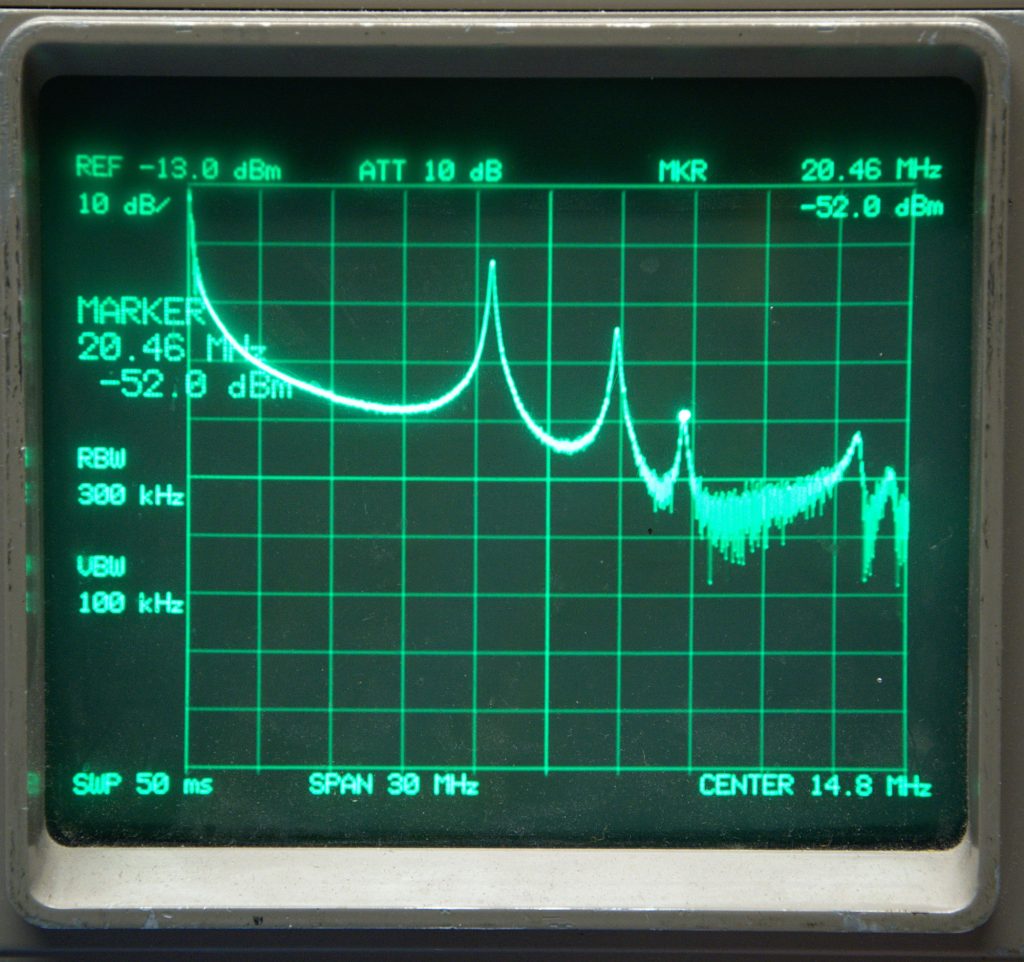
Again I recalculated the values for the 30mm ceramic body and changed the wire to 0.5mm diameter. The second peak is TOO close to the 17M band and it has to be changed / moved. The third peak is close to the 15M band but still well suppressed.
Some work to be done on this choke!