
Introduction
For my new to build HF PA I was looking for 3 turns counters for vacuum capacitor and / or a roller inductor. These vacuum capacitor do around 12-13 turns and a position readout is very desirable because you have three variables: the plate and load capacitor and the roller inductor.
A search on Ebay was easily done and several were found for astonishing prices. I needed three of them. For three I was looking at €300 and I had to be lucky with the customs.
I started thinking of making one myself. Adding a rotary encoder on the shaft would give me a very high resolution of 20 pulses per revolution. Mechanically it was easy to solve and had some advantages as well. One could build in stepper motors and control these to make a high speed tuning system.
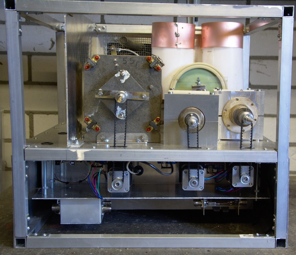
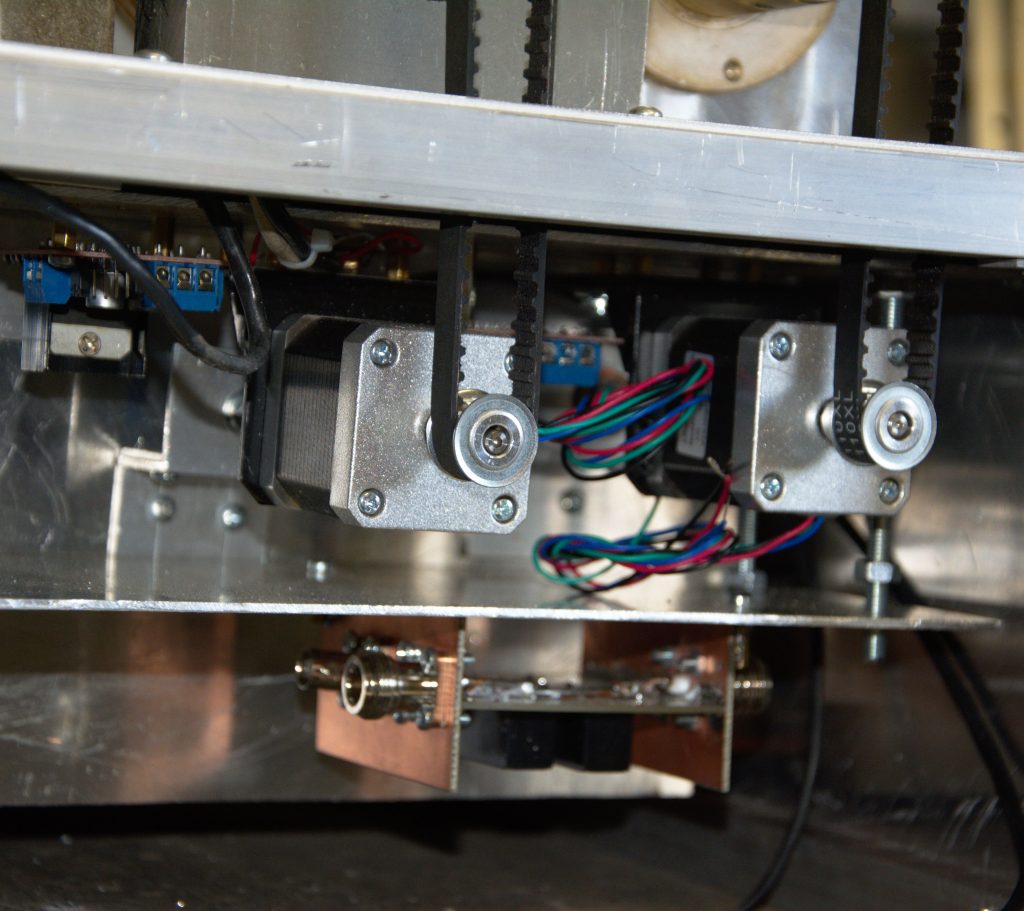
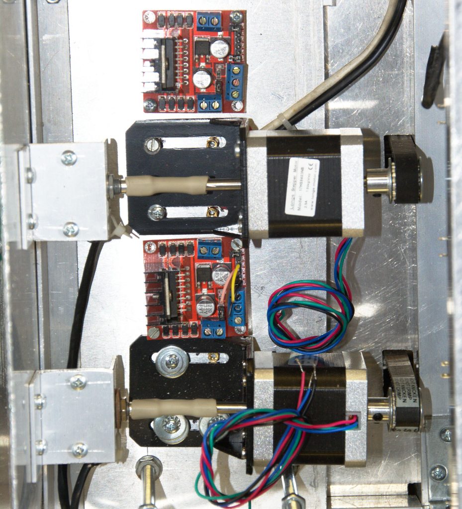
Mechanical
Below are some photo’s how the problem was mechanically solved.
Electrical
Electrically it was a problem. When switching of the amplifier the value of the counter had to be stored or kept in any other way.
- Use a battery to keep the value. OK but one needs to recalibrate when the battery is empty.
- Keep a small power supply running to keep the value, also OK but what would happen if the power was totally out?
- To use a supercap to store the value when the voltage is dropping. Power consumption is an issue, so one had to switch of the backlight and use parts that do not use a lot of energy in order to give the arduino time to save all to the internal EEPROM.
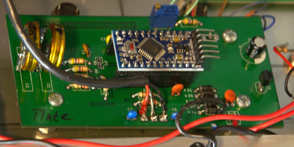
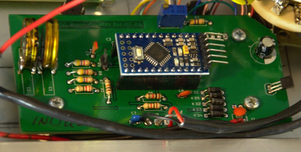
I decided to go this last route. As an energy saver I decided to use Arduino Pro Mini without the USB and to use some diodes in the hardware to control backlight. Saving to EEPROM starts when the voltage drops below 10V. The hardware was decided to like this:
Or HERE is a PDF Pulse_Counter_HF_PÅ
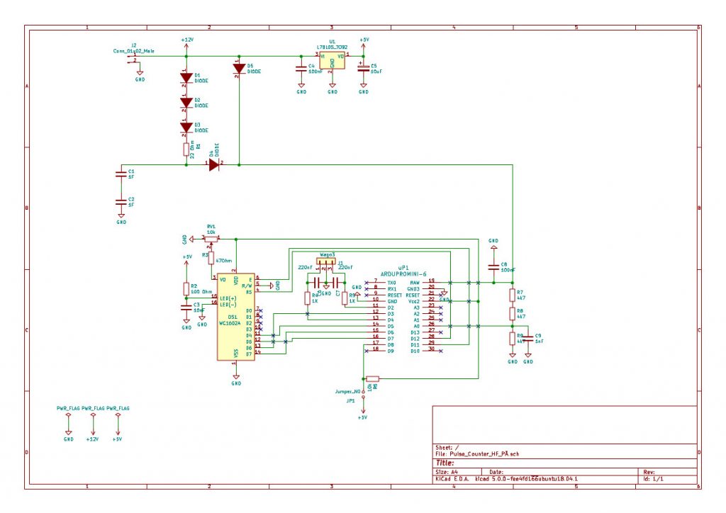
The three diodes in series lower the 12v by 1.8V. These supercaps take only 5.5V. The 12V feeds a 5V stabiliser IC, this is used to feed the backlight. Diode D5 feeds the system from the 12V supply when available. When the 12V drops the arduino will notice this as the voltage is measured on A0 via a voltage divider. And save the position to the EEPROM. The rotary encoder is connected through the 3 pin screw connector. Use a shielded cable to connect the encoder!
In the beginning some trouble showed up when switching the PA on. The arduino pro mini decided to die very quickly or would not perform as they should. Probably voltage peaks were the cause of the trouble. After adding a large inductor toroid (100uH) from an old PC power supply and a TVS diodes of 13Volts the problem was solved. These arduino pro-mini’s have a very poor regulator on the board, or it was a bad series…..Anyhow after the above modification nothing died!
For those interested a PCB is available for €10 + shipping costs. You can contact me via the “contact page”
The software
An attempt was made with an arduino mega to attach 3 encoders to one arduino on a 20 x 4 display. Using three interrupts. This proofed to be a disaster. The software would crash when using two interrups seldom but it was not reliable. Three interrupts was a disaster. The software would behave more organic. A choice was made to design a board with the arduino mini and a 16 x 2 LCD parallel display. All to speed things up. Software was based on a design found on the internet by Bart Venneker LINK
//*************************************************************************
// Based on an example for a rotary encoder
// taken from Bart Venneker 2015
// See http://youtu.be/KzT3aUE1-0Q for more info (in DUTCH!!)
// And more stolen ideas from the internet
//*************************************************************************
//
// Geert Stams, PA3CSG with LCD display readout, january 2018
// Thanks to Anton Mandos ON6NL for helping coding & throwing the broken Arduino’s in the bin
//
// The circuit:
// * LCD RS pin to digital pin 12
// * LCD Enable pin to digital pin 11
// * LCD D4 pin to digital pin 5
// * LCD D5 pin to digital pin 7
// * LCD D6 pin to digital pin 3
// * LCD D7 pin to digital pin 6
// * LCD R/W pin to ground
// * LCD VSS pin to ground
// * LCD VCC pin to 5V
// * 10K resistor:
// * ends to +5V and ground
// * wiper to LCD VO pin (pin 3)
// * Encoder connected to pin D2 and D4
// * Middle pin encoder connected to GND
//
//******************************************************************************************************
// include the library code:
#include <LiquidCrystal.h>
#include <EEPROM.h>
const int rs = 12, en = 11, d4 = 5, d5 = 7, d6 = 3, d7 = 6;
LiquidCrystal lcd(rs, en, d4, d5, d6, d7);
//define pins
#define ROTARYPLATEA 2
#define ROTARYPLATEB 4
//Choose the text for the display
//#define PLATE 1
#define INDUCTOR 1
//#define LOAD 1
long rotaryPlateCount;
int address = 0;
//***************************************************************
// SETUP
//***************************************************************
void setup() {
Serial.begin (9600);
pinMode(ROTARYPLATEA, INPUT);
pinMode(ROTARYPLATEB, INPUT);
pinMode(LED_BUILTIN, OUTPUT);
digitalWrite (ROTARYPLATEA, HIGH); // enable pull-up
digitalWrite (ROTARYPLATEB, HIGH); // enable pull-up
// set up the LCD’s number of columns and rows:
lcd.begin(16, 2);
// A little bit of PR
lcd.setCursor(0,0);
lcd.print(“Position Counter”);
lcd.setCursor(5,1);
lcd.print(“PA3CSG”);
delay(1000);
lcd.clear();
//print things on the lcd that donnot change
//first line
lcd.setCursor(1, 0);
#ifdef PLATE
lcd.print(” PLATE counter”);
#endif
#ifdef LOAD
lcd.print(” LOAD counter”);
#endif
#ifdef INDUCTOR
lcd.print(” INDUC counter”);
#endif
//read stored value
rotaryPlateCount = EEPROMReadlong(address);
Serial.print(“Read RotaryPlateCount “); Serial.println(rotaryPlateCount);
}
//************************************************************
// Main Loop
//************************************************************
void loop() {
// attach the interrupts for the encoders
attachInterrupt (0, rotaryTurn0, RISING); // interrupt 0 is pin 2, For rotary encoder
lcd.setCursor(7, 1);
lcd.print(” “);
lcd.setCursor(7, 1);
lcd.print(rotaryPlateCount);
Serial.print(“Print RotaryPlateCcount “); Serial.println(rotaryPlateCount);
//Write to EEPROM if supply voltage <10V
Serial.print(“AnalogVol “); Serial.println(analogVol());
if (analogVol() < 10) {
EEPROMWritelong(address, rotaryPlateCount);
Serial.print(“RotaryPlate written “); Serial.println(rotaryPlateCount);
digitalWrite (LED_BUILTIN, HIGH);
while(1) {}
}
}
//****************************************************************************
// Subroutine count the turns of the encoder
//****************************************************************************
void rotaryTurn0()//subroutine for the plate interrupt
{
// Interrupt Service Routine for a change to Rotary Encoder pin A PLATE
if (digitalRead (ROTARYPLATEB))
rotaryPlateCount–; // Turn it Down!
else
rotaryPlateCount++; // Turn it Up!
}
//******************************************************************************
// Subroutine write the EEPROM
//******************************************************************************
void EEPROMWritelong(int address, long value)
{
//Decomposition from a long to 4 bytes by using bitshift.
//One = Most significant -> Four = Least significant byte
byte four = (value & 0xFF);
byte three = ((value >> 8) & 0xFF);
byte two = ((value >> 16) & 0xFF);
byte one = ((value >> 24) & 0xFF);
//Write the 4 bytes into the eeprom memory.
EEPROM.write(address, four);
EEPROM.write(address + 1, three);
EEPROM.write(address + 2, two);
EEPROM.write(address + 3, one);
}
//*****************************************************************************
// Subroutine read the EEPROM
//*****************************************************************************
long EEPROMReadlong(long address)
{
//Read the 4 bytes from the eeprom memory.
long four = EEPROM.read(address);
long three = EEPROM.read(address + 1);
long two = EEPROM.read(address + 2);
long one = EEPROM.read(address + 3);
//Return the recomposed long by using bitshift.
return ((four << 0) & 0xFF) + ((three << 8) & 0xFFFF) + ((two << 16) & 0xFFFFFF) + ((one << 24) & 0xFFFFFFFF);
}
//*****************************************************************************
//SUBROUTINE VoltMeasurement
//read voltage on pin A0
//*****************************************************************************
int analogVol(){
int ADVol = 0; //input voltage on pin A0
int ValDig =0;
float VoltSup = 0;
ValDig = analogRead (ADVol);
VoltSup = ((ValDig * 5) / 1024.0);
VoltSup = (VoltSup * 3);
Serial.print(“Supply Voltage “); Serial.println(VoltSup);
return VoltSup;
}