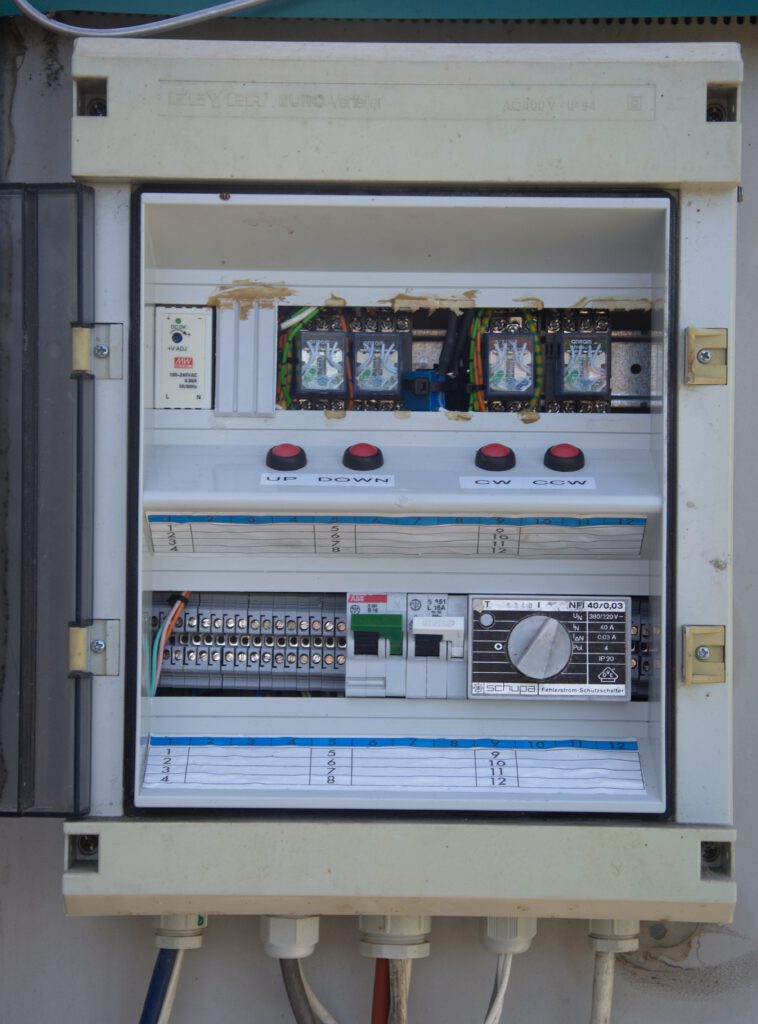
After 25 years my dish needed a new control box for the rotators, the old one was rather worn out. I kept the same AC motors as they performed very well over the last decades. I decided to put the control unit at the tower and to use a 5 wire cable to control the Az and the El rotators, switching a relay to ground.
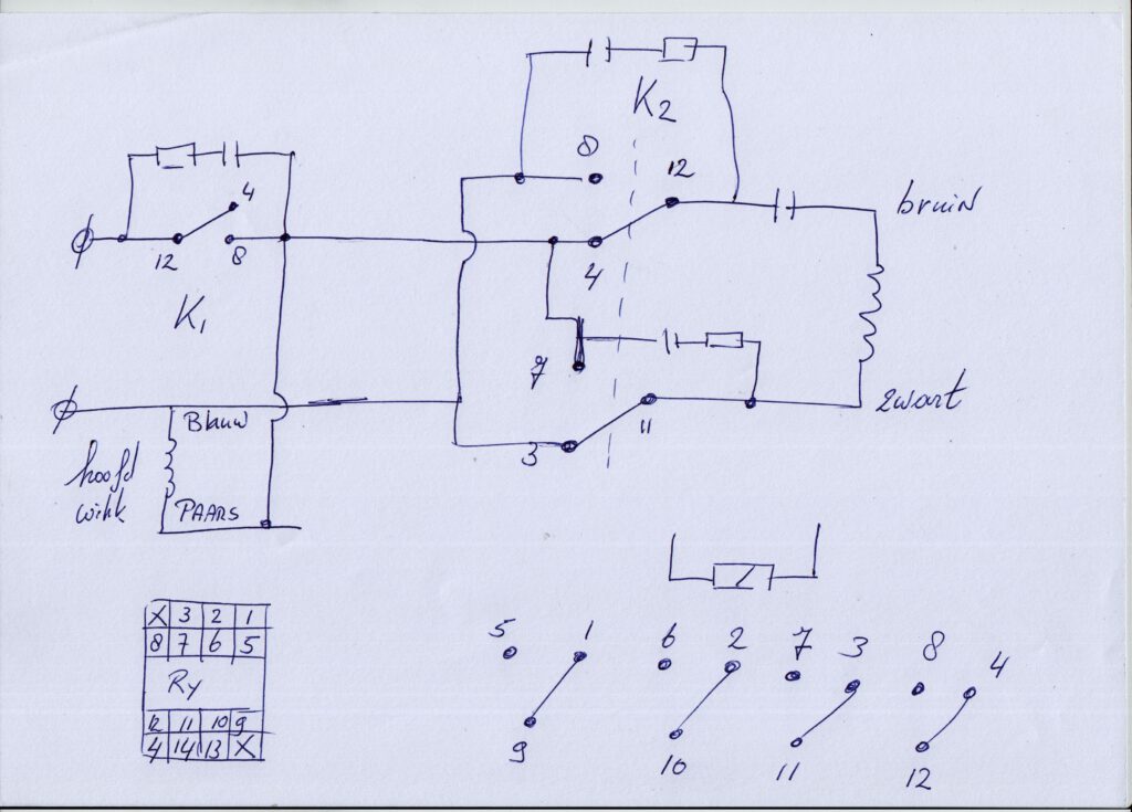
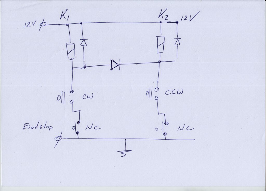
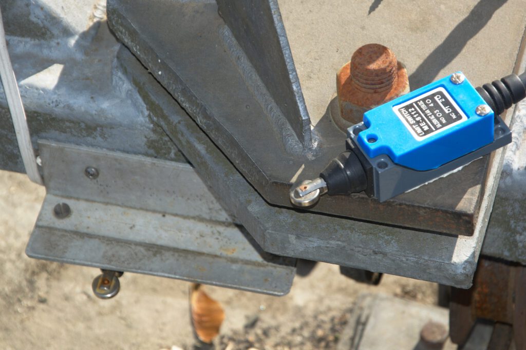
I added snubbers over the relay contacts, not only for the mains switch but also for the help winding. The last isn’t necessary probably. There is also a provision for mechanical end stops, so in theory nothing could happen.