
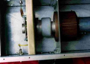
A GS35 amp fore 432 MHz, one of many designs. This design is well proven and simple to copy. The output of this amp will go above 2kW.
This is driving the tube to its limits. A solid 1.5kW can be obtained.
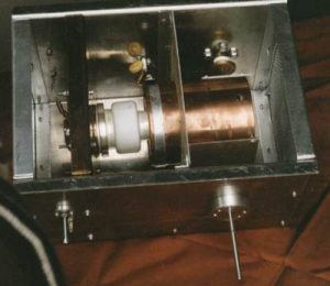
The dimensions of the box are 32 x 20 x 20 cm (h,w,d) Made of 3mm thick aluminium.
Grid plate is made out of 3mm brass.
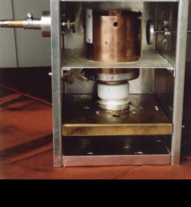
The plate line is a 10cm diam. copper tube 12cm long, from bottom of cooler to top of line.
Plate tuning disk is 50mm diameter opposite a 60mm x 60mm plate with a layer of teflon sheet fastened to it.
Loading disk is 35mm (+/- 5mm) diameter opposite teflon sheet mounted on anode line.
Air barrier is 1.6mm epoxy PC board with all copper stripped off.
Input tuned circuit is 10mm x 40mm brass strip with finger-stock connection to cathode. A 0.5-3pF capacitor is in series with the input, and C to ground is 2 disks, 30mm diameter.
Assembly:
First assemble the finger-stock in the brass plate and in the cathode PCB making the tube socket. Solder input L to the cathode board. Mount cathode on brass plate. Make sure that the tube fits correctly in the socket.
Mount brass grid plate in the aluminium housing. It is about 8cm from the bottom.
Drill holes for the input C and BNC input connector. Make sure that all connections are as short as possible!!!!
Drill holes for feed-through caps at the other side.
Complete anode line with insulation and plate C’s. Cut a number of slots in the copper about 3cm deep to make it fit around the GS35 cooler. A large hose-clamp will hold it in place. Use a 5cm PTFE stand-off at the end.
Push tube with plate line in socket and the air barrier and mark places where load, tune C and HT feed through have to be drilled. Mark place where air barrier plate has to be mounted.
Take tube out, mount air barrier and drill holes. Mount tuning and loading C’s and HT feed through.
Put tube with plate line back in and fasten it to the Bottom using a self tapping screw.
Finish input circuit soldering input series C to C to ground and to BNC connector. Mount cathode RFC’s (2W 47K resistor fully wound with 0.8mm enamelled copper wire). Solder plate RFC (lambda/4 wire and capacitor to ground 1nF)
Put end and bottom plates in. Place cover with blower on top.