
The old sequencer has been build by a large number of people. This went well with no problems, were heard about this design. It is fairly easy and straightforward. But sometimes there were feature requests. Basically these requests were all about the same problem:
When you touch your cw keyer the whole systems went into transmit. The same happens when your rig is in VOX mode and the there is some noise in the shack. For this problem several solutions were suggested. I incorporated these in the version II of the sequencer.
Solution one:
Make 4 instead of 3 outputs, the 4th output switches the key. No solution for the VOX problem. Unless you use the 4th output to enable key and microphone PTT
Solution two:
Yaesu transceivers have something they call a TX inhibit, as long as there is 12V on this TX-INHIBIT pin, the transceiver refuses to go to transmit. This is easily controlled by the Arduino. After all the 4 ports have switched you disable your TX-INHIBIT signal and it all will work. This could be done by the 4th sequencer output pin as well. But now it is on the sequencer board.
Solution three
The above solutions are no good for Icom or Kenwood users. They lack the TX-INHIBIT pin, but someone suggested to use the ALC-pin for that. Generating a low current negative voltage is easy with the 7660 series of IC’ s. Now the uncertain part…how negative this voltage should be. Icom seems to be around -3V, Kenwood 2000 should be around -8V. You can change the value of the variable resistor in output to adapt your voltage. Frank PA2M came to the conclusion the his Icom 9700 needed about 1mA on the ALC. I cannot test all these transceivers so you are on your own! This board will go up to about -9V .
Please be aware this ALC version is NOT tested with every transceiver. The voltage may vary also the current draw of your ALC circuit may affect the potmeter settings.
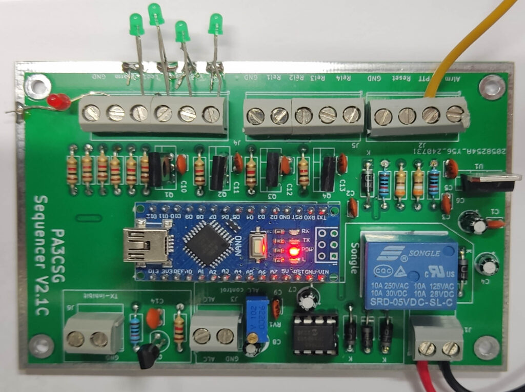
Can you use the Version II sequencer in the old Version I way? Yes: Just don’ t put the components for the TX-INHIBIT and ALC on the board. If you don’t want to use the number 4 output, just set the switching delay between port 3 & 4 to 0 (zero milliseconds). On the PCB the TX-INHIBIT & ALC component blocks are in a white square.
The rest of the functionality is the same. The Alarm port, when it turns to High (+5V) it will turn all the 4 outputs to Low without delay. The red led will light. A reset button to ground to reset the sequencer in case of an alarm.
A lot of people used the sequencer without the open collector on the board and used a (Chinese) relay board instead. For that reason an extra connector was put on the board. This connector can be used for the relay board or for leds or not at all.
A PCB for this sequencer will be available. You can sent an email to geert.pa3csg@ leavethisout gmail.com
The circuit of the Sequencer V II

The code for the new Sequencer V II
Make sure to set your own switching delays!
 /*

SEQUENCER Version 2.1C 8-8-2024

Sequencer adapted with 4 switching moments compared to 3 moments in the original sequencer
If you do not need 4 switching moments just change the int relaytime_3_4 = 0; // There will be no delay and relay 4 doesnot exist
IF ALC & TXinhibit are not needed, there is no need to change the software, You can omit the components on the PCB.  See printed text on PCB

Good luck!

73 Geert PA3CSG

*/

  //variables for the sequencer
  int txgnd=2; // on pin Digital 2
  int relay1=3; // on pin Digital 3
  int relay2=4; // on pin Digital 4
  int relay3=5; // on pin Digital 5
  int relay4=6; // on pin Digital 6
  int alarminput = 7; //on pin Digital 7
  int alarmled = 8; // alarmled on pin 8
  int TXinhibit = 9; // TXinhibit on pin 9 for Yaesu transceivers
  int TXalc = 10; // ALC switching on pin 10  for Icom & Kenwood transceivers
  int txgndstate = 0;
  int alarminputstate = 0;
 //**********************************************************************************************************
 // Set relay switching times below

  int relaytime_1_2 = 50; //time in ms
  int relaytime_2_3 = 50; //time in ms
  int relaytime_3_4 = 50; //time in ms
  int relayALC_TXinhibit = 50; //time in ms

  //**********************************************************************************************************

  void setup()  {
  //setup sequencer

  pinMode(relay1, OUTPUT); //relay 1
  pinMode(relay2, OUTPUT); //relay 2
  pinMode(relay3, OUTPUT);  //relay 3
  pinMode(relay4, OUTPUT);   //relay 4
  pinMode(txgnd, INPUT_PULLUP);
  pinMode (alarminput, INPUT); // initialize alarminput as input
  pinMode(alarmled, OUTPUT); //alarmled will light in case of alarm
  pinMode (TXinhibit, OUTPUT); //output pin for TXinhibit switching
  pinMode (TXalc, OUTPUT); //output pin for ALC switching

  digitalWrite(relay1, LOW);
  digitalWrite(relay2, LOW);
  digitalWrite(relay3, LOW);
  digitalWrite(relay4, LOW);
  digitalWrite(alarmled, LOW);
  digitalWrite(alarminput, LOW);
  digitalWrite(TXinhibit, LOW);
  digitalWrite(TXalc, HIGH);

  }


  void loop() {
Serial.begin (9600);

 // code for sequencer

txgndstate = digitalRead (txgnd);

    if (txgndstate == LOW) { // go to transmit
      digitalWrite(relay1, HIGH); //relay 1
      delay(relaytime_1_2); // Time between relay 1 & 2
      digitalWrite(relay2, HIGH); //relay 2
      delay(relaytime_2_3); // Time between relay 2 & 3
      digitalWrite(relay3, HIGH); //relay 3
      delay(relaytime_3_4); // Time between relay 3 & 4
      digitalWrite(relay4, HIGH); //Time between relay 3 & 4
      delay(relayALC_TXinhibit); // Time between relay 4 & ALC and TXinhibit switching
      digitalWrite(TXinhibit, HIGH);
      digitalWrite(TXalc, LOW);
      //Serial.println

    }

    if (txgndstate == HIGH) { // go to receive
      digitalWrite(TXinhibit, LOW);
      digitalWrite(TXalc, (HIGH));
      delay(relayALC_TXinhibit); // Time between relay 4 & ALC and TXinhibit switching
      digitalWrite(relay4, LOW);
      delay(relaytime_3_4); // Time between relay 4 & 4
      digitalWrite(relay3, LOW); //
      delay(relaytime_2_3); // Time between relay 2 & 3
      digitalWrite(relay2, LOW); //
      delay(relaytime_1_2); // Time between relay 1 & 2
      digitalWrite(relay1, LOW); //

    }


   alarminputstate = digitalRead (alarminput); //EMERGENCY NO DELAY TIMES!

    if (alarminputstate == HIGH) {
      digitalWrite(TXinhibit, LOW);
      digitalWrite(TXalc, HIGH);
      digitalWrite(relay4, LOW);
      digitalWrite(relay3, LOW);
      digitalWrite(relay2, LOW);
      digitalWrite(relay1, LOW);
      digitalWrite(alarmled, HIGH);
      delay(10);
      while(1) { } //endless loop to stop

    }


  }