This page reports on an ongoing project. It is not finished yet. It is very interesting to work on.
Wave-guide switches are hard to get. The 10 GHz ones are hard to find, but the 24 GHz wave guide relays are nearly impossible to find. Good reason to give it some thought if we can make one ourselves. The basic idea was that production could be done in a makers lab or in a fablab.
A quick search on the internet offers one design by W1RIL unfortunately a SK. The page is hosted by the WA1MBA and can be found here.
http://www.wa1mba.org/wr42sw2.htm
Version 1
Things were started slowly with some help from my son in law Bas who is a mechanical engineer the first drawings were made. Things started in the summer of 2023. With the coming of a 3D printer first items became physical and could be improved.
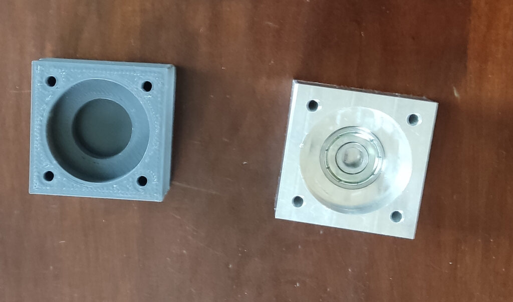
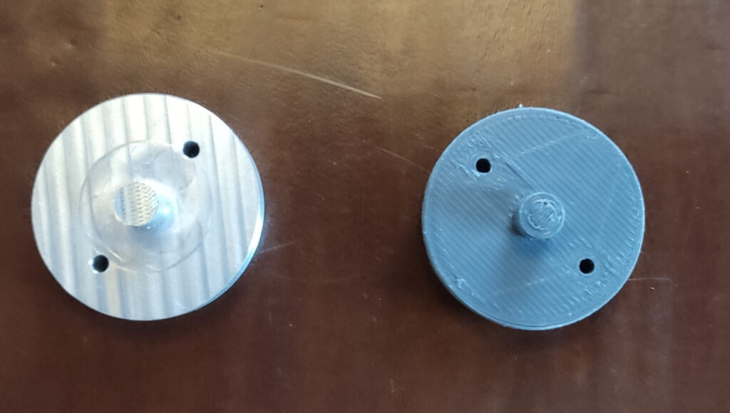
The next step was to make the rotor drawing and have that made in the fablab.
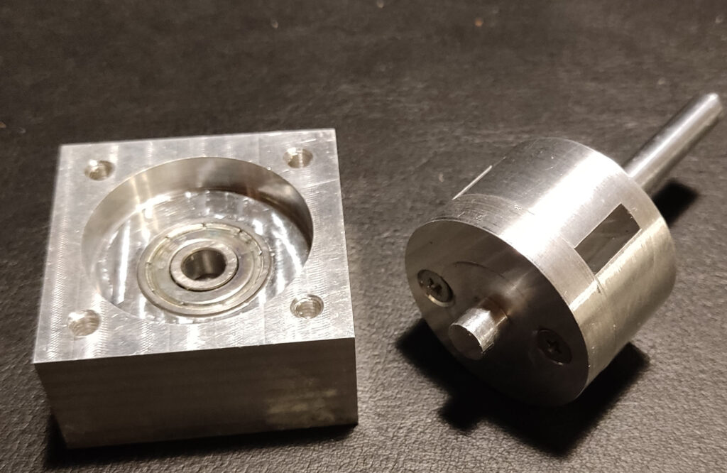
By putting the switch together I quickly noticed that some dimensions were not correct. The holes for mounting the WG-flanges were not deep enough so the whole body was enlarged now measuring 50 x 50mm. The rotor remained the same. 2 out of 4 parts were redesigned and milled.
Version 2
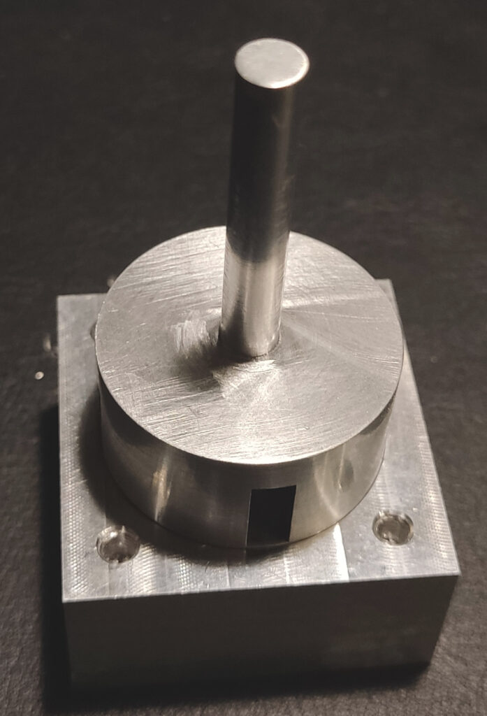
When the parts arrived it was quickly fitted together. To make it fit nicely some minor changes were necessary. The whole thing didn’t rotate smooth so 0.1mm was removed in several places. It all came out very nicely and really something to be proud of. Next will be the RF testing of the switch!
The measurements
The measurements were first done by Jack PE1KXH. The results look very good and promising. The isolation measurements are limited by the dynamic range of the measurement and a bit uncertain. Dorsten 2024 was the opportunity to redo the measurements.
Part 4 Measurements at the Dorsten UKW Tagung 17 Feb. 2024
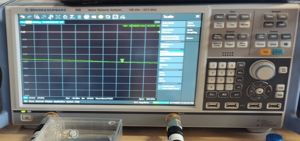
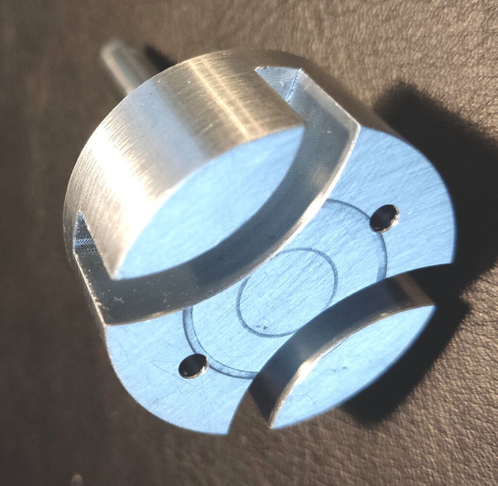
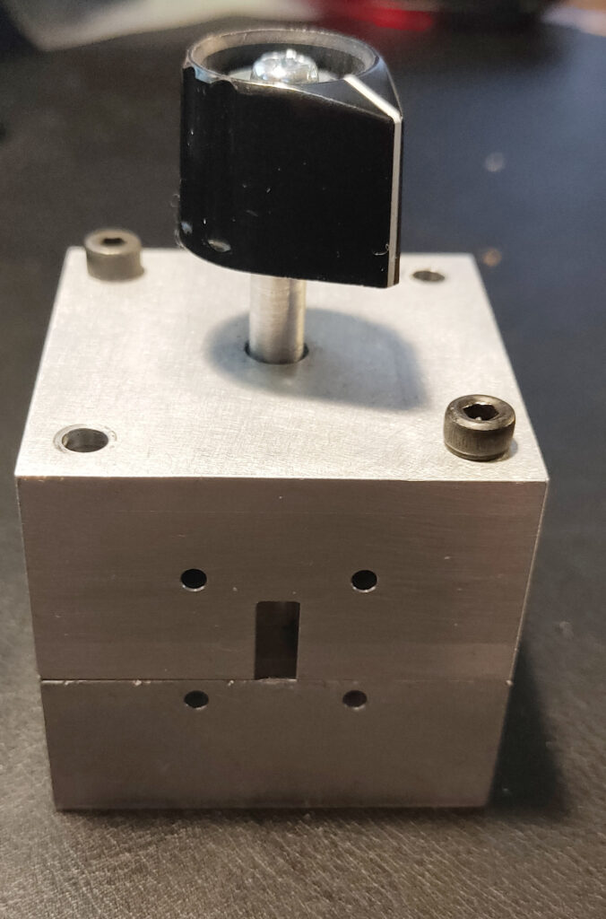
Conclusion was that the isolation between two ports of the waveguide switch was not sufficient. It was around -40dB. At least not for EME powers >15W for the usual 2W that would do the job. Improvement was needed! As seen in several commercial waveguide switches the rotor was slitted to improve isolation. With some simulation help (Thanks Willy&Gerald) the rotor was newly made according to the next photo:

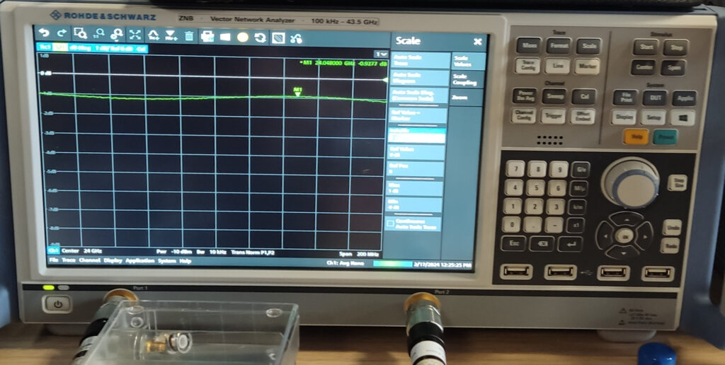
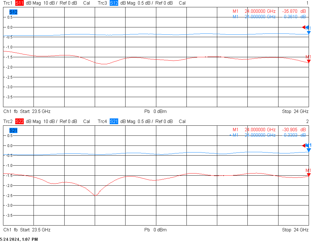
This resulted in nice results. Measurements were carried out first by Jack PE1KXH and after that by Markus. The switch proved to be acceptable. Insertion loss 0.3dB Isolation 51dB and matching was nice as well on the 4 ports. A pity was that the network analyzer did not go above 24GHz. Limited by software in the the VNA. Anyway no complains who can measure up to 24GHz? Special thanks to Markus DG9BFJ and Jack PE1KXH
The below photo shows the port #1 to port #2
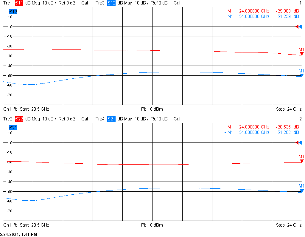
The following picture shows the isolation:
A small video showing the switch.