
Here follows a photo description of a 2 x GS35 PA for 144 MHz. Beware this is not a fully tested design!
There are no more / better design details than these pictures.You should know what you are doing when you start copying this PA. Else you should NOT try this design. The voltages these PA works with are lethal and leave no room for harmless experiments.
This design has been working for me the last 8-9 years. I have never run it at full ratings but it delivered “cool” power for the JT65b mode on 144. The capacitors in the plate line have to be of high quality. These “orange ones” lasted several years but appeared not to be good enough. What happens if you use the “wrong” coax relay is easy to see. This relay was build for SHF and not for QRO on VHF. 
With this PA I completed my DXCC on 2 meters.
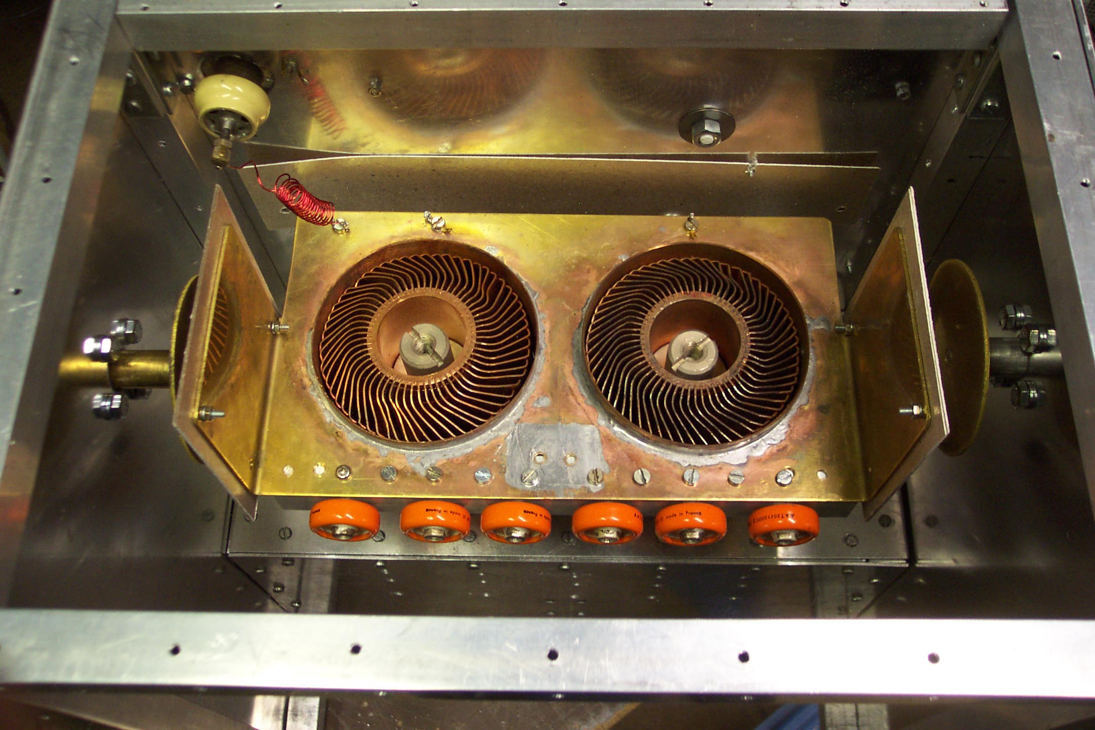
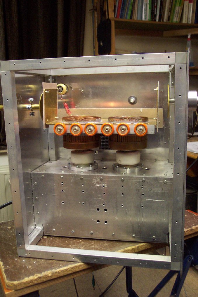
On the above photo you see the two anodes of the GS35. On the right is the plate tuning for the amplifier.
On the left is the output coupling. The up left corner shows the feedthrough capacitor. The choke is a lambda / 4 choke. About 50cm wire wound on a 10-12mm diameter. Isolation between tuning C and load C is made of mica. These mica sheets are available for repairing microwave ovens. This is a high quality insulator. The only problem is to find a supplier for it.
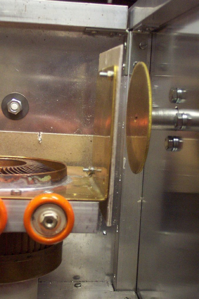
The picture above shows a detail of the plate tuning capacitor.
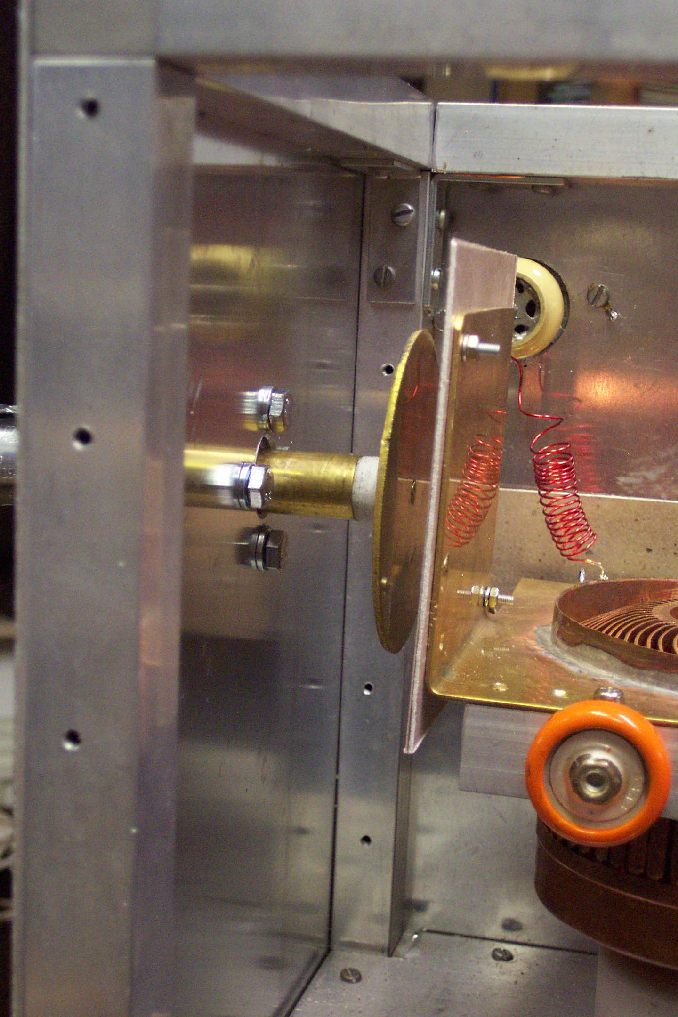
Detail of the output coupling capacitor.
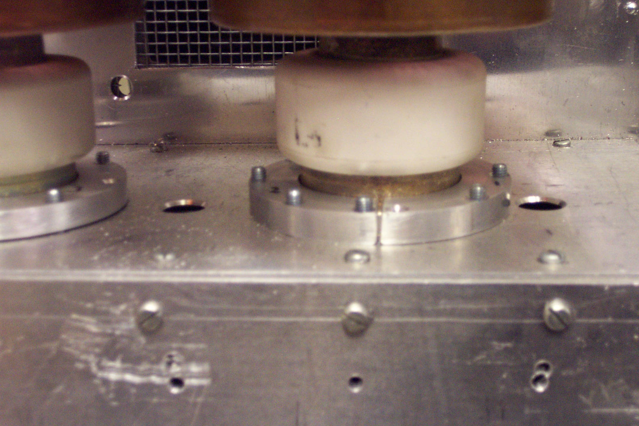
The grid ring mounting construction detail.
The complete anode compartment with the plate line removed.
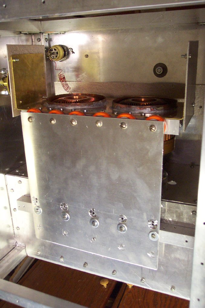
Now with the plate line mounted. As you see I had to move the shorting bar to find the resonant point. The second try was already OK. Must be pure luck.
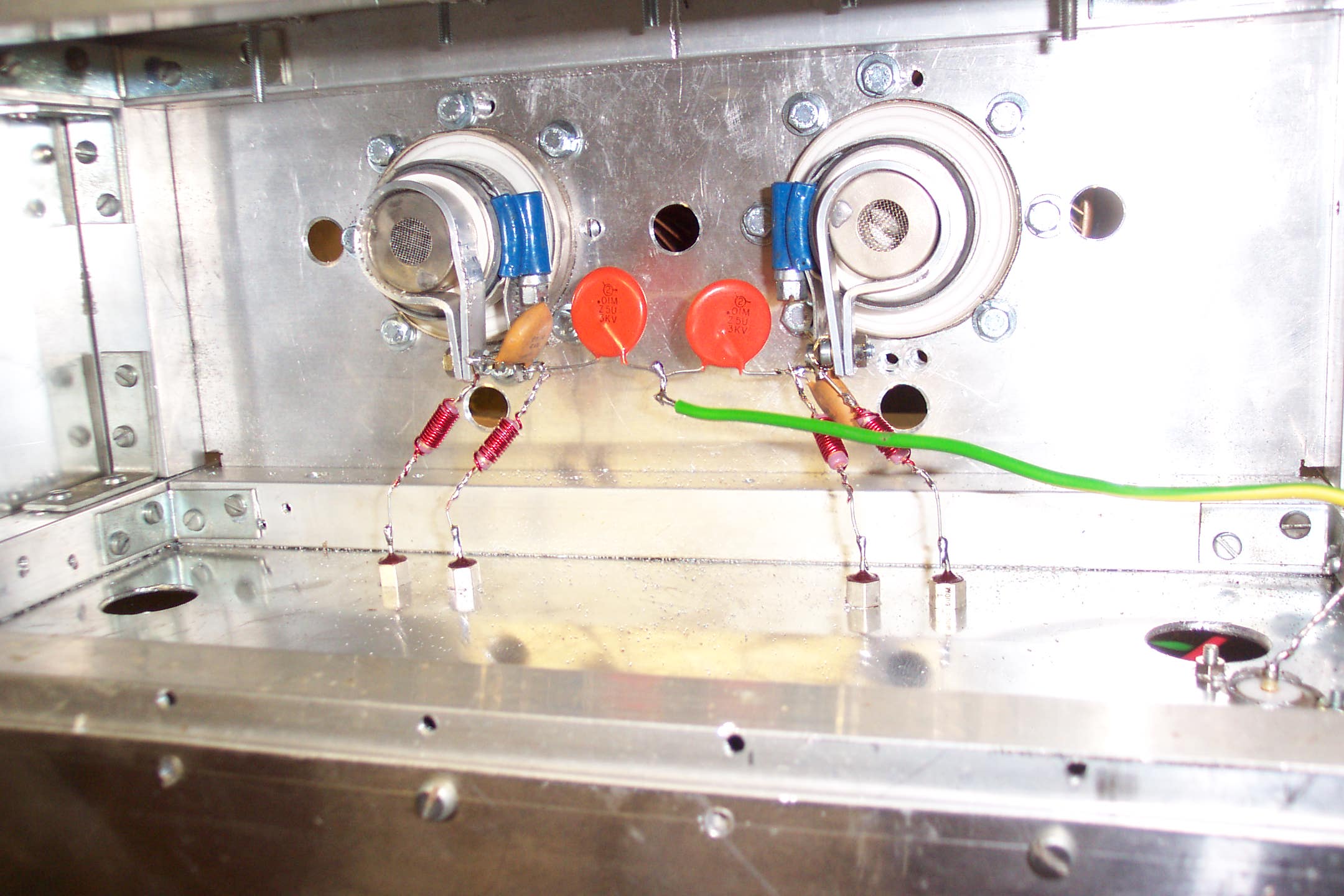
The cathode compartment. It again is kept rather simple. The input consists of a series capacitor, capacitor to ground and a series L. (Seen from the input) The L is the yellow and green wire. Make sure there is some airflow on the cathode side as well. Drill some holes around the grid ring. It looks like some 12mm holes are drilled here. The chokes are 47K or 56K 2W resistors fully wound with 1mm enamelled wire. This should give a rather broadband decoupling. Use some good feed-through capacitors.

Another view of the cathode compartment.
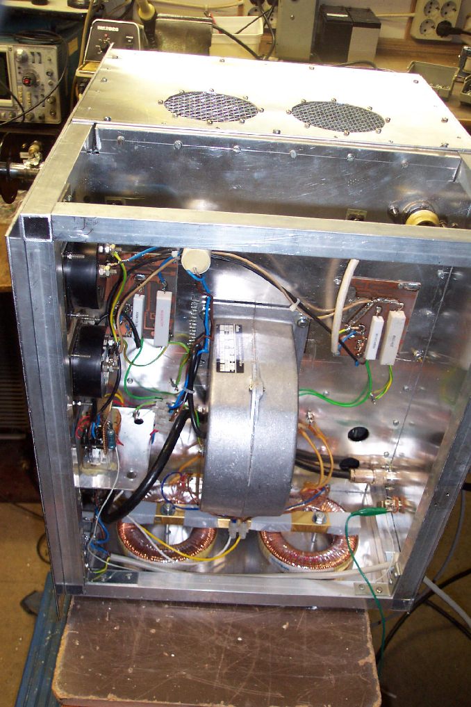
The blower / bias part of the amplifier. On the bottom 2 heater transformers. Top left and right 2 bias boards. On the left you can see the 2 plate current meters with the transmit / receive switching.
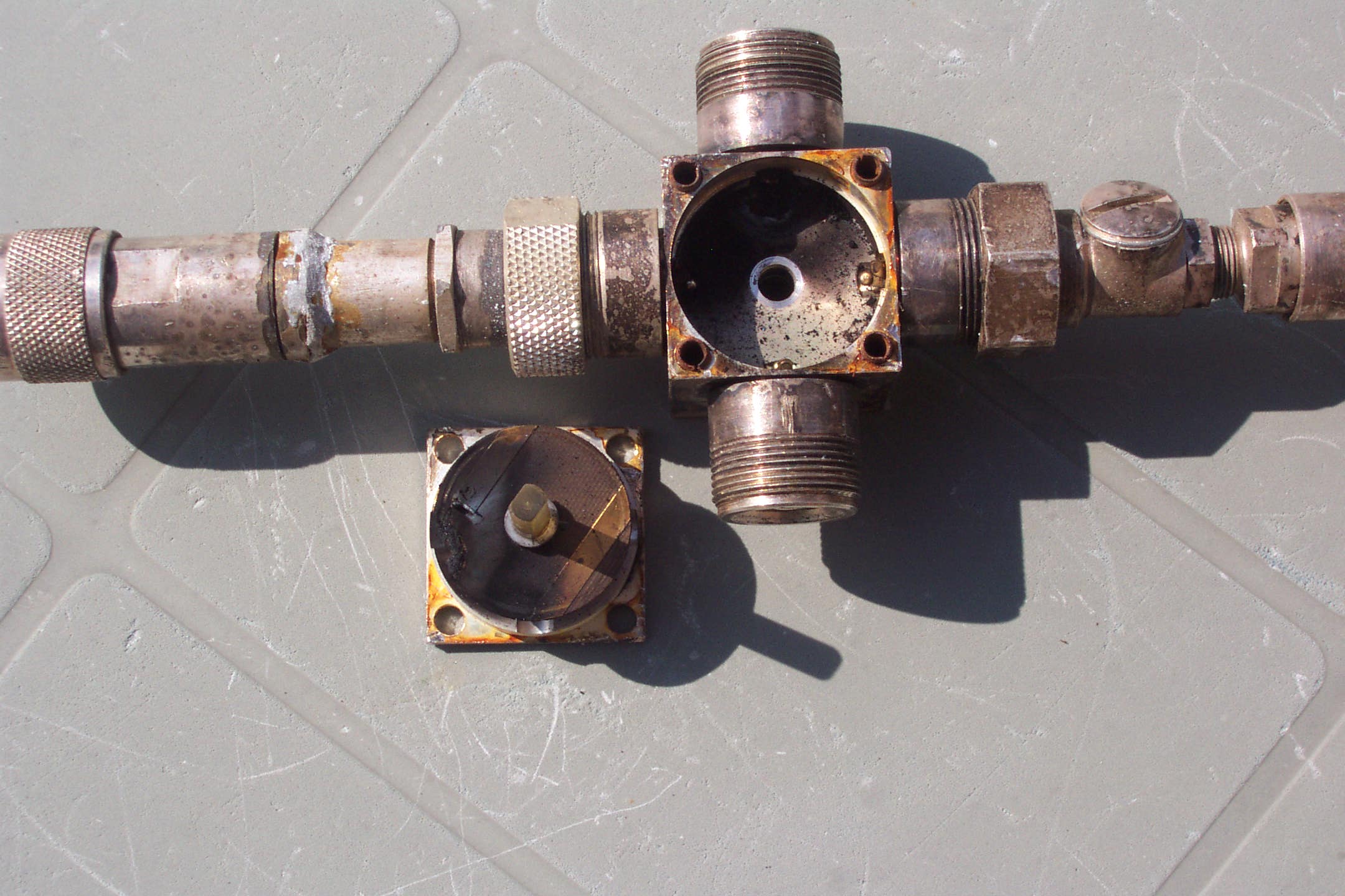 The unlucky relay.