To build a solid state amplifier today, one has the availability of many fets. Preferably Ldmos as this is the most sturdy and the most forgiving to mistakes from the operator. The normal attenuation of a push pull amplifier on the HF bands is about 30-40dB. Thus requiring a filter.
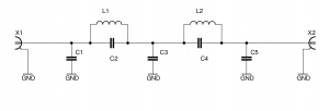
The choice has been made for elliptic filters. These provide the steepest stop band attenuation.
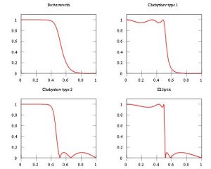
The graph above has been taken from the Wikipedia website. One can adjust the notches for the 2nd and 3rd harmonic to obtain extra attenuation.
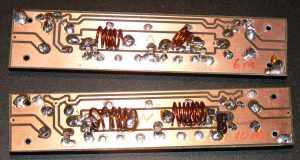
I never had my play with these filters. I started with the design in the ARRL 2010 handbook. But as this was not to my likings I designed my own. One filter for one band. The crosstalk on the original design was rather high on 6M so I decided to try a different approach. A filter for each band and all on separate PCB boards with two relays on each PCB. This would make the filter fully flexible and extend-able. The same PCB with relays can be used to make a bypass for the filter.
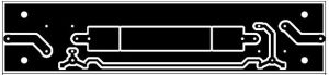
PCB is not too scale.
The PCB is a double sided epoxy FR4 type. The relays are soldered on the bottom part. The relay used here is the Omron G5LA. It is available in different voltages. The solder dots are 1mm brass rivets used as grounding contacts.
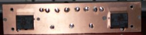
All the rest of the components are soldered to the top layer. Each relay is bypassed with a 100nF capacitor and a 1N4148 diode.
Alignment
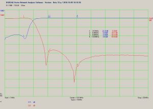
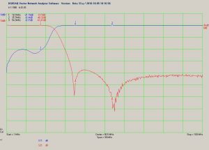
For the alignment of the filters, the home brew network analyser from Jack, PE1KXH was used. This fine piece of equipment is available from SDR-kits. For more information check the references chapter or Google for DG8SAQ
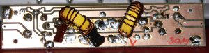
First the L1-C2 and the L2-C4 have to aligned to match the second and third harmonic. If you increase the inductance of L1 and L2 too much your matching of the filter will go bad. Adjust the air wound inductors by bending, pulling them apart or pushing them together.
The coils wound on the toroids are more difficult to tune. Move the winding on the toroid. This has only minor effects. If this does not result one has to adapt the capacitor value. Fortunately these are the lower frequencies and therefore the less critical.
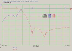
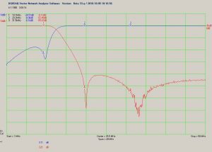
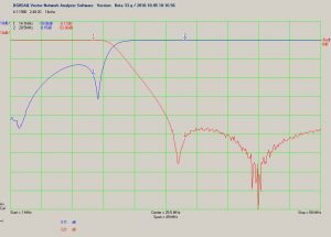
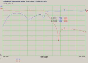
Results
Below are some measurements
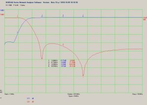
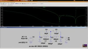
The free software LTspice does a great job also simulating this kind of RF problems: See the screen shot below for the 7 MHz filter.

|
5 pole Cauer Low pass filters |
|||||||
|
Frequency |
C1 |
C2 |
L1 |
C3 |
L2 |
C4 |
C5 |
|
160M |
680pF |
130pF |
4,2uH |
2000pF |
3,3uH |
560pF |
560pF |
|
80M |
560pF |
100pF |
2,0uH |
1000pF |
1,5uH |
330pF |
470pF |
|
40M |
330pF |
56pF |
1,06uH |
560pF |
831nH |
130pF |
220pF |
|
30M |
150pF |
22pF |
765nH |
330pF |
603nH |
80pF |
100pF |
|
20M |
100pF |
20pF |
578nH |
253pF |
455nH |
56pF |
150pF |
|
17M |
100pF |
15pF |
443nH |
200pF |
349nH |
68pF |
56pF |
|
15M |
68pF |
22pF |
382nH |
180pF |
301nH |
47pF |
47pF |
|
12M |
68pF |
12pF |
334nH |
150pF |
263nH |
33pF |
47pF |
|
10M |
68pF |
12pF |
307nH |
150pF |
239nH |
56pF |
56pF |
|
6M |
36pF |
6,8pF |
157nH |
70pF |
125nH |
30pF |
27pF |
|
5 pole Cauer Low pass filters |
|||||||
|
Frequency |
C1 |
C2 |
L1 |
C3 |
L2 |
C4 |
C5 |
|
160M |
680pF SM |
130pF SM |
22wdg op T94-2 rood 1.5mm dia |
2000pF SM |
20wdg op T94-2 rood 1.5mm dia |
560pF SM |
560pF SM |
|
80M |
560pF SM |
100pF SM |
16wdg op T94-2 rood 1.5mm dia |
1000pF SM |
13wdg op T94-2 rood 1.5mm dia |
330pF SM |
470pF SM |
|
40M |
330pF SM |
56pF SM |
11wdg op T94-2 rood 1.5mm dia |
560pF SM |
10wdg op T94-2 rood 1.5mm dia |
130pF SM |
220pF SM |
|
30M |
150pF ATC100B |
22pF ATC100B |
10wdg op T94-6 geel 1.5mm dia. |
330pF SM |
9wdg op T94-6 geel 1.5mm dia. |
80pF 33pF ATC100b 47pF ATC100B |
100pF SM |
|
20M |
100pF SM |
10pF SM 10pF SM |
9wdg op T94-6 geel 1.5mm dia. |
220pF SM 33pF ATC100B |
8wdg op T94-6 geel 1.5mm dia. |
56pF ATC100B |
150pF ATC100B |
|
17M |
100pF ATC100B |
3,9pF ATC100B 12pF ATC100B |
8wdg 15mm dia. 20Mm lang 1,8mm dia |
100pF SM 100pF SM |
7wdg 15mm dia. 20Mm lang 2mm dia |
68pF SM |
56pF SM |
|
15M |
68pF SM |
22pF ATC100B |
7wdg 15mm dia. 20Mm lang |
180pF SM |
6wdg 15mm dia. 20Mm lang |
47pF ATC100B |
47pF ATC100B |
|
12M |
68pF SM |
10pF SM 2,2pF ATC100B |
7wdg 15mm dia. 20Mm lang |
150pF ATC100B |
6wdg 15mm dia. 20Mm lang |
33pF ATC100B |
47pF ATC100B |
|
10M |
68pF SM |
12pF ATC100B 3,3pF ATC100B |
7wdg 8mm dia. 1,3mm |
150pF ATC100B |
6wdg 8mm dia. 1,3mm |
56pF ATC100B |
56pF ATC100B |
|
6M |
33pF ATC100B 3,3pF ATC100B |
6,8pF ATC100B |
5wdg 8mm dia. 1,3mm |
22pF ATC100B 47pF ATC100B |
3wdg 8mm dia. 1,3mm |
27pF ATC100B 3,9pF ATC100B |
27pF ATC100B |
|
5 pole Cauer Low pass filters |
|||||||
|
Frequency |
C1 |
C2 |
L1 |
C3 |
L2 |
C4 |
C5 |
|
160M |
680pF |
130pF |
4,2uH |
2000pF |
3,3uH |
560pF |
560pF |
|
80M |
560pF |
100pF |
2,0uH |
1000pF |
1,5uH |
330pF |
470pF |
|
40M |
330pF |
56pF |
1,06uH |
560pF |
831nH |
130pF |
220pF |
|
30M |
150pF |
22pF |
765nH |
330pF |
603nH |
80pF |
100pF |
|
20M |
100pF |
20pF |
578nH |
253pF |
455nH |
56pF |
150pF |
|
17M |
100pF |
15pF |
443nH |
200pF |
349nH |
68pF |
56pF |
|
15M |
68pF |
22pF |
382nH |
180pF |
301nH |
47pF |
47pF |
|
12M |
68pF |
12pF |
334nH |
150pF |
263nH |
33pF |
47pF |
|
10M |
68pF |
12pF |
307nH |
150pF |
239nH |
56pF |
56pF |
|
6M |
36pF |
6,8pF |
157nH |
70pF |
125nH |
30pF |
27pF |