For operation on 2320MHz I needed a receive power splitter for my IF 144 MHz. It had to cover the 100-150 MHz range.
The first idea was to build a resistive power divider but I ended up with a Wilkinson divider. Because of the long pieces of coax I decided
to build the Wilkinson divider out of lumped parts. In order to keep small.
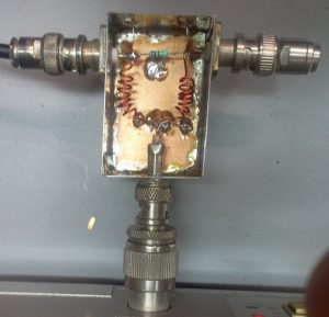
It had to be a quick and dirty project, so I used a tinned box.
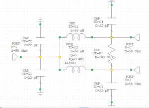
The circuit diagram:
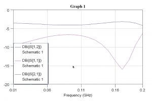
The simulation showed the following result:
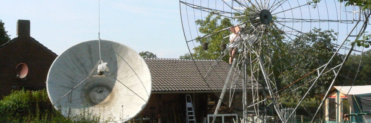
It was decided to keep things simple. I used 4 capacitors, each 22 pF and 2 small air coils. I had to fiddle a bit because the box was a bit to big.
I ended up with 6 turns on a 4mm diameter about 12mm long. As you can see on the photo I had to stretch the coils a bit, I tried to make it a bit more wideband.
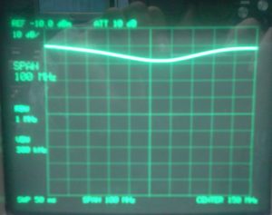
Measurements:
Centre frequency 150 MHz and a span of 100 MHz.
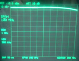
The isolation between the ports is shown below: