 For my Arduino power / SWR meter needed a coupler for 1.5 – 30 MHz. It was easy to find a design. I used the coupler as published in the ARRL 1992 Handbook. According to this publication it was suitable for power levels up to 1500 W. Well even below that level it went faulty.
I decided to build my own with bigger toroids. I obtained a few T130-2 from Amidon and tested the coupler. It was not a very succesfull test. The directivity was very poor and the coupler was not suitable for any SWR measurements.
Luckily Olof PA0ZOZ published his experiments in the Dutch ham radio magazine “Electron” January 2014. In this article Olof showed some light on the design parameters of these couplers. After some e-mails with Olof I was able to design a coupler suitable for my needs. Olof was very helpfull and his information was very correct. Some of his information is repeated here. Thanks Olof!
The coupling factor.
If we want to obtain a coupling factor of -33dB we will have 1/2000 of the power coupled from the main line. The voltage is SQR 2000 = ~45 We would need 45 windings on the toroid. Please note that the more windings on the toroid the lower the coupling will be. Attemps with more than 45 turns on the toroid proofed to be a disaster. Using the T130-2 the directivity was way below what was needed. Removing turns from the toroid improved the situation a bit but not enough to produce something usable.
After numerous experiments and several toroids I came to the conclusion that the bigger the core and the more windings the directivity got worse and the max usable frequency got lower. I concluded that the capcitances between the wire was the cause of my bad coupler. I had to find something optimum in size of the toroid and the number of turns. More turns would be less power in the core and so a higher max power for the coupler. A bigger core would also allow more power but both increase the capcitances. An optimum had to be found!
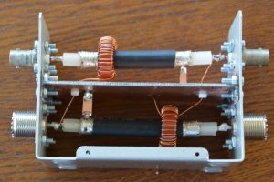
I ended up with a T94-2 core and 30 turns. This proofed to be the biggest usable toroid and the maximum number of windings. This coupler has been in use for several months now and I am still happy with it.
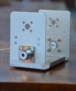
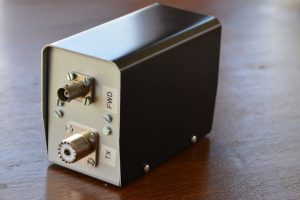
I used a standard TEKO BC1 box dimensions 62 x 118 x 84 mm
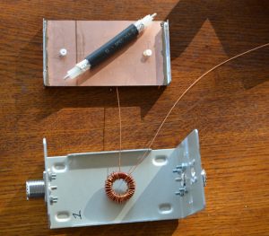
The following photographs should enable you to reproduce the coupler without to much difficulty.
The first picture shows the parts in use.
As coax I use the RG214 if you don’t wind the wire to tight on the core it will fit very nice. Otherwise you might have to use some tape.
The following photo shows the drilled box from one side. The other side is the same.
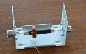
The first core is soldered in. Note one end of the winding goes to ground, the other goes to the connector on the other half of the coupler.
After that the ground shield is screwed in. I use a piece of copper clad PCB board.
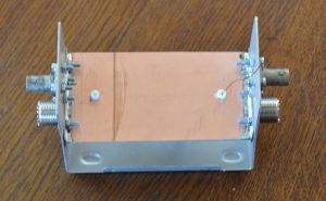
Than the upper part is installed
Note that only ONE side of the coax braid is grounded.
The finished result.
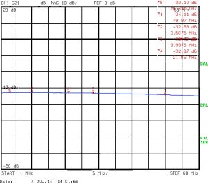
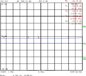
My good friend Jack PE1KXH was so kind to make some professional measurements. Measurements were done on 2 couplers.
This is coupler 1. It shows the forward coupling.
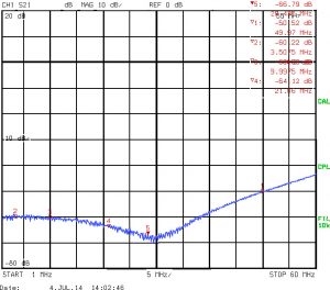
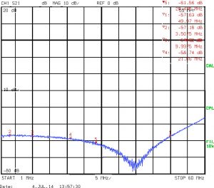
The following plot shows the coupling to the Reflected port. From these values you should substract the values from the first graph. This will give you the directivity.
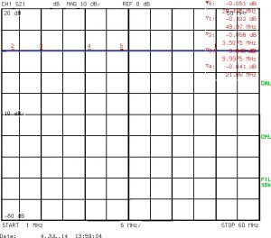
The following plot shows the insertion loss. Very low!
In the same sequence the values for coupler 2.