
A GS35 amp fore 144 MHz. I once got a hand made drawing of this amplifier. It originates from ex UV1AS, RX1AS (thanks RW1AW for correcting this).
I modified the input circuit and changed the construction of the output circuit a little.
This design will run at very high efficiency (65%) and is simple to copy. The output of this amp will go above 2kW.
See below for the modification made by F1CXX to this amplifier.
According to his data his amplifier is working very well also.
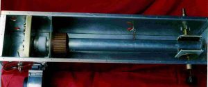
The dimensions of the box are 83 x 17 x 17 cm. Made of 3mm thick aluminium.
Grid plate is made out of 2mm brass.
The plate line is a 55mm diam copper tube 53cm long, from top of the cooler to end of line were the capacitors are.
Plate tuning disk is 80mm diameter opposite a 100mm x 100mm plate with a layer of teflon or mica sheet fastened to it.
Loading disk is 80mm diameter opposite a 100mm x 100mm plate with a layer of teflon or mica sheet fastened to it.
Air barrier is 1.6mm epoxy PC board with all copper stripped off.
Input tuned circuit is 17cm long copper wire 2mm diam. . A 0.5-3pF capacitor is in series with the input, and C to ground is an air C about 20pF.
Assembly:
First assemble the finger-stock in the brass plate and in the cathode PCB making the tube socket. Solder input L to the cathode board. Mount cathode on brass plate. Make sure that the tube fits correctly in the socket.
Mount brass grid plate in the aluminium housing. It is about 12cm from the bottom.
Drill holes for the input C and BNC input connector.
Drill holes for feed-through caps.
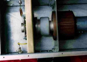
Complete anode line with insulation and plate C’s. The connection from the line to the GS35 is a machined part, one end to fit the plate line, the other end machined down to fit the GS35. The nut holding the GS35 cooler is removed and the plate line is used instead. Use a PTFE stand-off at the end.
Push tube with plate line in socket and the air barrier and mark places where load, tune C and HT feed through have to be drilled. HT feed through is about 31cm from box end. Mark place where air barrier plate has to be mounted.
Take tube out, mount air barrier and drill holes. Mount tuning and loading C’s and HT feed through.
Put tube with plate line back in and fasten it to the Bottom using a self tapping screw.
Finish input circuit soldering input series C to C to ground and to BNC connector. Mount cathode RFC’s (2W 47K resistor fully wound with 0.8mm enamelled copper wire). Solder plate RFC (lambda/4 wire and capacitor to ground 1nF)
Put end and bottom plates in. Place cover with blower.
F1CXX design amplifier.
3-6-2017
Franck sent a link containing a full description for his amplifier. Click HERE
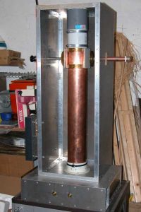
Franck did use the same design but made the anode line completely from a 10cm wide tube. This has the following advantages:
The tube is better cooled as the copper pipe acts as a cooler.
There is no air blocking plate any more
Because of the larger tube you will have to adapt to the impedance for the tube and this is what Franck did. He made the box bigger.
(the box is 308 x 308 mm and plate line is 100 mm diam)
As long as you maintain the impedances of the plate line the same you can almost use all kind of tubing.
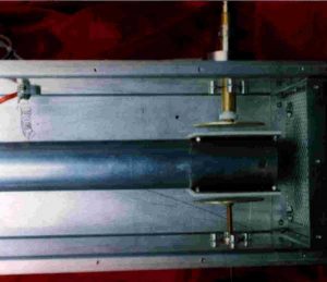
The plate line of the F1CXX amp. Note the bigger box.
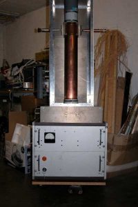
Complete view
A nicely made output coupler.
For the output, the the connector is 7/16.The inner tube is 8mm. The outer
tube is 18/20 and the guide is 20/22 copper tube.
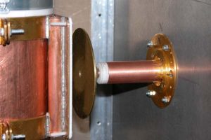
To stay within the spec of the connector a 7/16 has to be used.
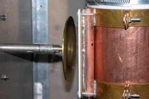
The plate tuning. Look how clever made the movable plates on the end of his plate line. In this way he can adjust the length of the plate line easily.
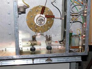
The input circuit of the F1CXX amp.
5 September 2010 Franck submitted a nice drawing of his amplifier.
You can access it f1ccx