A 2 stage 2M bandpass filter using helical s.
Note there is a new article about this filter with more information click HERE
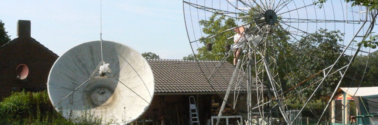
On my moonrise I have a clear view from my moonrise to the west. There is a TV transmitter about 10km away causing some unwanted products in my 2M receiver. A simple 2 stage helical filter BEHIND my mgf1802 preamp solved the problem completely. The filter is mounted at the feed-point of my 8.5M dish between the first and the second stage preamp. ( I have a 50M cable run!)
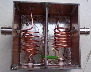
The filter is build in a standard tin box 74 x 74 x 50 mm. Constructing this prototype I used some junk-box FR4 PCB material. Make sure that both sides are grounded.
The inductors consist of 6 turns 2mm diam wire on a 16mm diameter.
The capacitors can be any type about 5pF.
The input is about 1/4 turn from the ground end.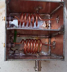
Capacitors are placed in the centre of the box.
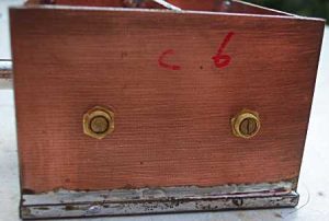
Note the grounded ends are NOT in the centre of the box but have an off-set of 8mm (halve of the coil diameter). grounded side view
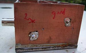
The green wire is a 2mm diam wire. (See first photo) This wire takes care of the coupling between the 2 coils. Here I wanted to have sharp filter with some losses as my preamp has enough gain. But with a rather sharp slope, and, as good as possible, attenuation of the 175 MHz TV transmitter and the 93 MHz FM radio transmitters. Making this green wire 6mm longer results in an about zero passband loss but a 10dB worse attenuation on the above mentioned frequencies.
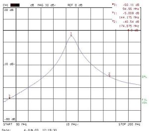
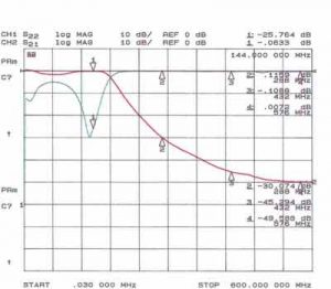
Plot of the above filter. 5dB passband loss. 40dB attenuation on 175 MHz and 60dB attenuation on 95 MHz. Resulting in a small but effective filter for mounting at the feed-point.
Measurements by Jac Smeets, PE1KXH.