144 MHz Bandpass filter revisited
The 144 bandpass filter as shown on my website (here) has been a very popular article. It was the most visited page in years! And indeed after every preamplifier a filter is needed to filter the passband and prevent overloading.
Regularly I received questions about the filter, how to use it on other frequencies, if it would be OK to use this or that. In fact the filter is very forgiving and easy to build and tune. Another item is that you can almost control all the parameters of the filter with a minor change.
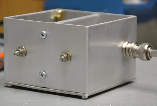
When a friend needed a couple of filters I decided to do a few more measurement on the filter and to produce the results here. I started with the normal 144 version of the filter: 6 turns on a 16mm diameter in a box of about 70 x 70 x 50 mm. I used 3pF tubular capacitors from the junk box. These were used in the older TV-tuners and may be hard to find these days.
The results of my efforts is shown in the next photo’s:
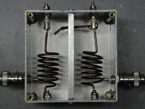
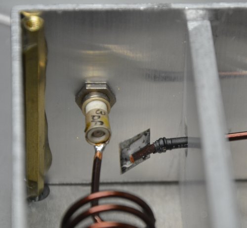
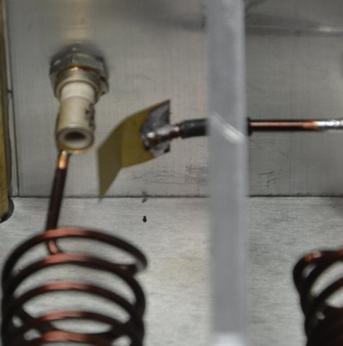
Or the inside which is more interesting:
Note the input taps are about 1/2 winding from the ground end. Capacitors are 3pF each. Note the wire, going from the right compartment to the left chamber. This wire is isolated with a bit of heat-shrink and makes a very very small capacitor coupling the signal from one helical to another. This small capacitor determines the loss of your filter and also how steep your filter is. Remember there is nothing like a free lunch. A steep filter will have more losses.
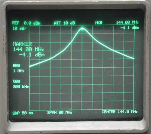
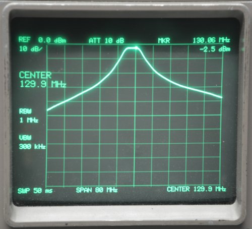
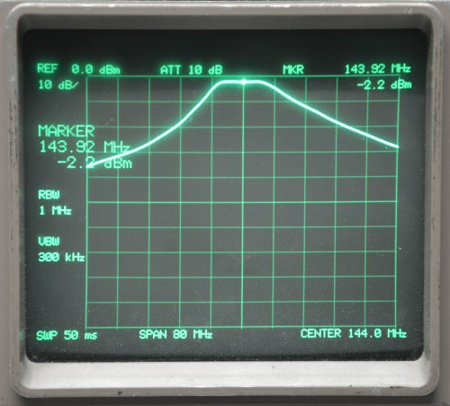
The coupling wire as shown in the picture above will provide a filter like below. Each vertical division is 10dB and horizontal is 8 MHz. Loss is about 4dB and at 108 MHz it has a loss of more than 45 dB. Note the slope is steeper on the low side.
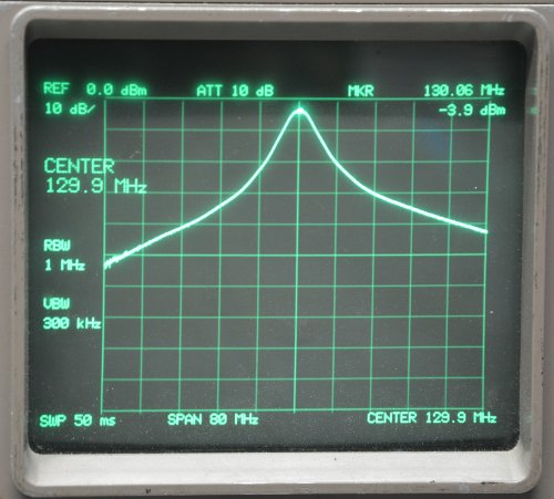
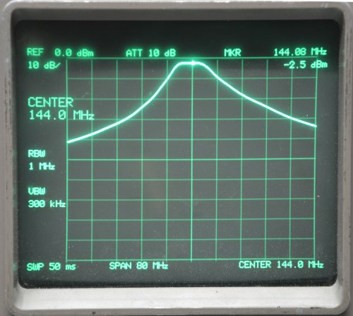
Given this configuration, over what frequency range can one tune the filter? It appears to be rather tunable. The following plots show the limits of the filter without changing anything. On the low side it will go down to 130 MHz.
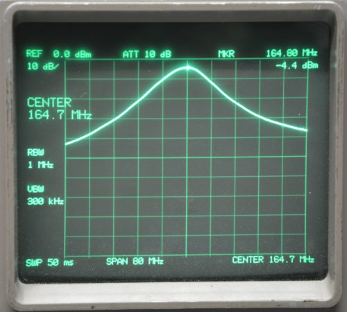
On the high side it will go up to 165 MHz all without a change and with a 3pF capacitor. Again horizontal 8MHz per division, vertical 10dB per division.
The next attempt will be to make the losses less and to make the filter a bit wider. I changed the coupling wire, I soldered a 8 x 8 mm wide copper vane on the wire and did the same measurements. The vane is still some 10 mm from the capacitor and it is still a very very small capacitor.
The losses will go down from 4dB to some 2 dB, about 1.5dB. The plot on 130 MHz: You note directly that the filter is much wider on the top and reasonable flat.
The plot on 144 MHz:
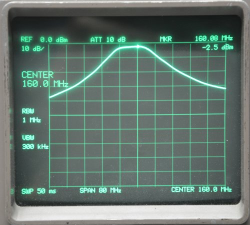
And the plot on 160 MHz. Note I could not get the wider version up to 165 MHz any more.
Another attempt to make the filter a bit wider. A brass plate (about 2 x 1cm) is soldered to the wire.
And the plot that goes with that:
The filter can be modified for 70 & 50 MHz use as well.
The 70 MHz version can be found HERE
The 50 MHz version can be found HERE