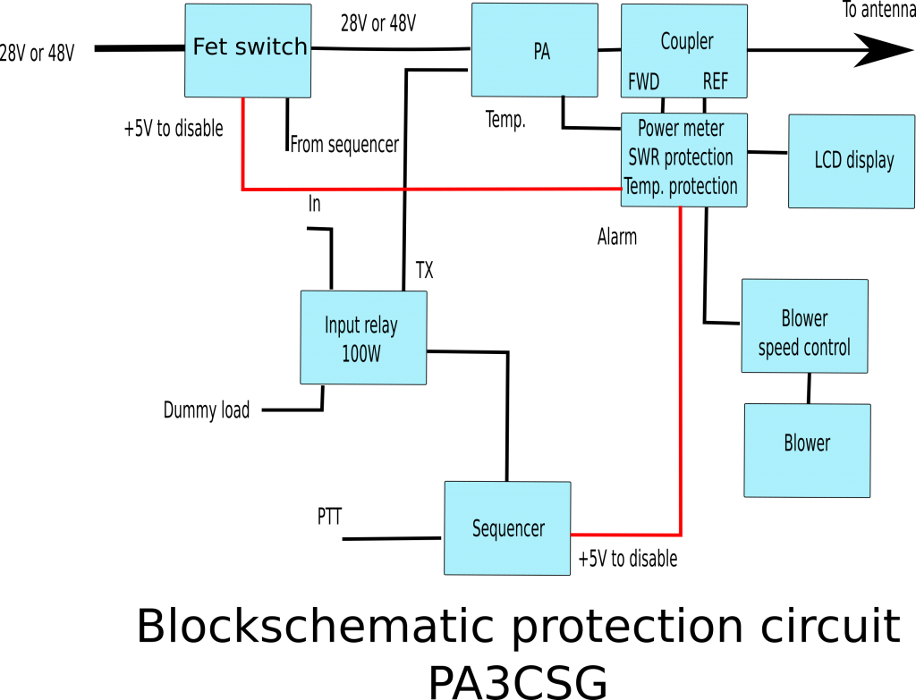
In order to provide a more clear overview on the protection system. You will find the blockdiagram below:

It consists of the Power / SWR meter as the heart of the unit. An new article is in preparation.
The sequencer article can be found HERE
The FET switch article can be found HERE
The Power / SWR meter detects the alarm sends it to the sequencer the sequencer disables the input relay, so drive power will go to the dummy load and the PTT is disabled.
The voltage supply for the amplifier is switched off by the FET Switch
PCB’s for most of these are available. See the for sale section HERE
